This is nothing I use 600.000 uf in some amps.
Yeah I have a Pass UGS with close to 500K UF, but still if you short 10K it make s a pretty big bang, snd the damage to a watch or dropped tool would be pretty ugly.
Hello to all . The original uses resistors MPS 25 which is 6.5 mm long, power 0.6 watts, I want to use TAKMAN resistors, but they have 9 mm long, power 0.5 watts, they do not fit in. The question is whether it is possible to use these resistors (and other better ) power of 0.25 watts, their length is also 6.5 mm?:смущенный:
You should specify which positions are you talking about. Some of the resistors do not dissipate any significant power and for them it really does not matter.
For most positions it is also not a problem if the resistors are raised from the board and the leads bent in order to accommodate the length.
I mean, put on the main board of the amplifier resistors 0.25 watts instead of 0.6 watts, which resistors 2 watts and 5 watts to leave unchanged.🙂
You can do this selectively. Some resistors around the input/dc contol, etc can be any wattage. The NFB 7.5k resistors and the base stoppers for the outputs should be 0.5W minimum.
All is clear, thank you🙂 And can you write according to the scheme (if not laziness) which ones can be reduced to 0.25 watts?
Last edited:
Hi. Almost done doing the assemnly of Ver1 & Ver2 PCB. I made a few changes to the Ver2 BOM. I'll send a copy to those that bought the pcb from me.
BTW I still have a few of the Ver2 (Prototype) in stock. Send me an email if interested.
Thanks
SB
BTW I still have a few of the Ver2 (Prototype) in stock. Send me an email if interested.
Thanks
SB
Heatsink
Anybody know if all the MJE transistors need heatsink? I guess only the drivers just before the outputs?
Anybody know if all the MJE transistors need heatsink? I guess only the drivers just before the outputs?
Anybody know if all the MJE transistors need heatsink? I guess only the drivers just before the outputs?
The ones closest to the input, I believe Q5, Q6, do not need cooling.
Thanks I asked because I mounted it on a 3 mm alu plate. I ****** up the 3 mm screw it had to be glued at the top.
Thanks I asked because I mounted it on a 3 mm alu plate. I ****** up the 3 mm screw thread it had to be glued at the top. Plate was to soft.
DC adjustment circuit.
Hi can anybody help?
Do I have to mount the Pot for DC adjustment and R 101 102 if I do not wish to use The DC adjustment pot? I ask because I have half of the very high DC out without these components. clock 3.30 in Copenhagen.
Hi can anybody help?
Do I have to mount the Pot for DC adjustment and R 101 102 if I do not wish to use The DC adjustment pot? I ask because I have half of the very high DC out without these components. clock 3.30 in Copenhagen.
At some stage i played with that. No problem removing that circuit, provided you tie up the bases of the input transistors to ground through some resistor.
If the resistor value is low enough the offset can be quite stable. The only issue was i didn't really like the sound, perhaps because of the ground return of this resistor. The ground layout of this board follows the mindless ground plane concept which is far from ideal. The input ground, thanks to the DC compensation network is virtual, which solves the ground plane issue quite well.
If the resistor value is low enough the offset can be quite stable. The only issue was i didn't really like the sound, perhaps because of the ground return of this resistor. The ground layout of this board follows the mindless ground plane concept which is far from ideal. The input ground, thanks to the DC compensation network is virtual, which solves the ground plane issue quite well.
Analog_sa you mentionned at some point of the thread that R101, R102 can be lowered to about 68K, and that the offset pot can be 20K. Is this correct or that's the 'low enough version' that doesn't sound as good?
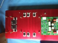
Tested my mods of Mark Johnson Soft start pcb to add the 'Overtemp' shutdown using a N.C. temp sensor, and it is working perfectly. Making progress on building a test prototype for the amp that will allow comparing both Ver1 and Ver2 pcb...
Tested my mods of Mark Johnson Soft start pcb to add the 'Overtemp' shutdown using a N.C. temp sensor, and it is working perfectly. Making progress on building a test prototype for the amp that will allow comparing both Ver1 and Ver2 pcb...
At some stage i played with that. No problem removing that circuit, provided you tie up the bases of the input transistors to ground through some resistor.
If the resistor value is low enough the offset can be quite stable. The only issue was i didn't really like the sound, perhaps because of the ground return of this resistor. The ground layout of this board follows the mindless ground plane concept which is far from ideal. The input ground, thanks to the DC compensation network is virtual, which solves the ground plane issue quite well.
Thanks now I am waiting for resistors. Will not use the pot at all but the servo. And no Supercapacitor.
For your info I received directly from a contact in China, the set of matched semi they sale over there to build the DartZeel. Since I already curve traced and matched my own set from original parts bought from Newark/Mouser, I tested the semi I received. First good news, the parts I received seem to be original, laser engraved logo, exactly same body, legs, etc... The HFE are similar, and if you look only at the HFE value using a simple transistor tester they are indeed matched.
But they are not curve matched, as we can expect. Further more for my own set I matched the small signal transistors on the Curve tracer, then again using the same Ic value as in the circuit, I fine tuned the match using the 'Transistor Matcher' PCB, for value under 2mv.
So my kit will be pretty close for the small signal transistors, and even if these transistors have a small impact on the resulting THD% result, I hope that will improve the DC stability.
To resume the Chinese semi set I received is not complete garbage, seem to use original parts as well and can probably be used with resonable results. Not sure about the sound though, I'll use my own matched sets.
Last edited:
It is clearly limited in power, especially with difficult speakers. Bass is nothing to write home about, even compared to very cheap amps.
Is it possible to selectively improve these areas without spoiling the good bits is something i don't know. The 458 sounded good to me but i have never heard it in the same system as a 108.
If the 108 series 2 experiment turns out unsuccessful it won't be a big disappointment. Have built dozens of unsuccessful amps in the past 😀
Great Info, Thanks Algar

They are same marked HFE, but since HFE value changes with the actual current that the part is, it is really not that useful. The curves were not that matched. Don't forget either that NPN and PNP are not the same HFE in particular with power transistor. It is almost impossible to match NPN and PNP type, neither necessary in the output stage.. . They were genuine parts at least and will work in the circuit...
If you're building the ver2, then you need matched pair of the parallel output transistor... Don't know if these advertised pair were matched or not, since they were NPN and PNP, I would be surprised they are...
If you're building the ver2, then you need matched pair of the parallel output transistor... Don't know if these advertised pair were matched or not, since they were NPN and PNP, I would be surprised they are...
Last edited:
- Home
- Amplifiers
- Solid State
- Dartzeel amp schematic - build this?