One of the early builder of the Ver2 PCB reports pretty good results. BTW there is no fault on the pcb and the amp is working fine, and is stable.
Here some of his comments:
- nfb resistors R6/R7 need to be raised to 91 ohm. (slight change from the 458 it was based on...) Will send a revised BOM to my buyers...
-footprint of supercaps should not cover any solder joints as the caps are flush with the board (Should be improve on a second version of this pcb, but it is working as it is, just make sure to insulate the super cap body (that is ground) from the pcb...
- Done some measurements. It appears very close to the published specs for the Series 2. No Stereophile measurements are available for this amp to make a detailed comparison
-No issues with setting offset and bias at all.
-Done only a short listen, still breaking in. Seems to have more authority and dynamics and less clear upper midrange/highs. The principal character of sound is very similar to the old 108. It seems considerably better than the old 108 with a second added pair of transistors.
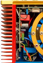
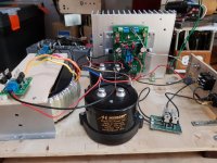
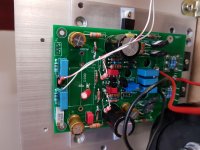
He also reports that the second pairs of transistor under the board are a close fit, but can be adjusted with bent legs. Check the included picture, seem like I need to rotate the bias transistor if I make a second version of this pcb...
So it seems the Ver2 is pretty good, and it is a working prototype.
Still have a few of the the pcb in stock. Let me know if you want to try them...
SB
Here some of his comments:
- nfb resistors R6/R7 need to be raised to 91 ohm. (slight change from the 458 it was based on...) Will send a revised BOM to my buyers...
-footprint of supercaps should not cover any solder joints as the caps are flush with the board (Should be improve on a second version of this pcb, but it is working as it is, just make sure to insulate the super cap body (that is ground) from the pcb...
- Done some measurements. It appears very close to the published specs for the Series 2. No Stereophile measurements are available for this amp to make a detailed comparison
-No issues with setting offset and bias at all.
-Done only a short listen, still breaking in. Seems to have more authority and dynamics and less clear upper midrange/highs. The principal character of sound is very similar to the old 108. It seems considerably better than the old 108 with a second added pair of transistors.
He also reports that the second pairs of transistor under the board are a close fit, but can be adjusted with bent legs. Check the included picture, seem like I need to rotate the bias transistor if I make a second version of this pcb...
So it seems the Ver2 is pretty good, and it is a working prototype.
Still have a few of the the pcb in stock. Let me know if you want to try them...
SB
Attachments
Why do you think that dartzeel nhb-108 model two contains supercaps ?...
-footprint of supercaps should not cover any solder joints...
SB
( E.g 2pcs 6800uF/6.3V capacitors are used in the NFB in cth-8550 and lhc-208 also. )
The two nfb paths are separated in dc by the bias spreader and that is why you cannot use a single cap as in the original 108. Or is there more to the question?
I think what shany is trying to say is, why don’t we think that the 2 6800uf 6,3V in the original model 2 is the 2 “supercaps” and not in form of the AVX type.
I think it’s possible he his right.
I think it’s possible he his right.
Last edited:
Seems to have more authority and dynamics and less clear upper midrange/highs.
That was clearly preliminary. Listened some more through difficult 4ohm speakers and frankly, it has been disappointing.
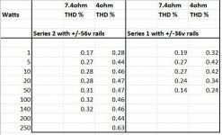
Just finished some distortion comparisons against the original 108 clone. Basically the new one is a bit worse across the board and at the most usable power range 5 -10W it has a similar thd, but clearly worse spectrum.
Earlier on in this thread Selfy mentioned that it is peculiar how the amp with the less sophisticated VAS would also sound great at much higher power and i now fully agree with him. No idea if the real Series 2, or the 458 are built around this concept, but this certainly sounds nothing like a real 458 which i have listened to on many occasions. Even worse, the 4ohm performance has more unpleasant distortion than the original clone.
Apart from that the amp is flawless 🙄 stable offset, bias, frequency range above 300kHz, damping factor as per specs, perfect 10kHz square wave, works fine in capacitive loads with no Zobel or inductor.
The "original clone" runs at a low supply voltage, so no measurements above 50W. My high power loads are not quite standard at 7.4ohm/4ohm and the max power into 7.4ohm on the Series 2 was limited by the maximum voltage output of the soundcard.
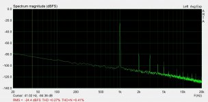
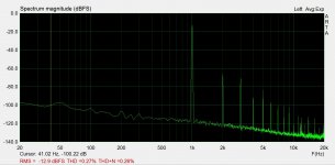
The distortion spectra @5W/7.4ohm for both amps are also attached.
Attachments
analog_sa, thank you for testing the alleged v.2 and sharing the results with us.
Although I had my doubts about the "Hungarian" circuit I really hoped it might sound better than 108 v.1 🙁
I may try the original Revox circuit, with NFB only at the VAS. I am also considering to try some "improvements" on the emitter follower stage...
PS: Are those Caddocks you are using for the emitter resistors of the output transistors?
Last edited:
Gents: 3 years ago I built the V1 of a kit. (The one with in-built speaker protection, relay etc). Its been working fine since and I like the sound. usage is near-field as PC speaker amplifier. Single output pair.
The issue is sometimes on one channel I will hear pops and crackles (static), it comes in waves then pops to complete silence. it comes on after a few minutes and goes away for an hour or so. happens sometimes... not always and on one channel only.
Is this related to DC offset (stays less than 10mV) or something else? (e.g is the PC's PSu feeding some HF into the amplifier since they are both plugged into the same mains sockets?
PS: Are those Caddocks you are using for the emitter resistors of the output transistors?
Тhey are. 0.22ohm, which is the reason for the highish output impedance of 0.33ohm, same as the original 108 S2.
Hi anybody got recommends for Supercapacitor?
It seems the Avx bestcaps I use sound ok, nothing scandalously inferior compared to my cap free clones as far as midrange and tonality, perhaps a bit more fog in the highs. They seem to live much shorter lives than standard electrolytics though, if this is a consideration. Why not just use normal electrolytics?
It is obvious, you do not want to use the original parts, so you do not get dartzeel sound....No idea if the real Series 2, or the 458 are built around this concept, but this certainly sounds nothing like a real 458 which i have listened to on many occasions. ...
Dartzeel do not use Vishay-Dale, Caddok and others.
Actually, you do not build dartzeel clones, rather these amps are another sort of amps with dartzeel schematics.
Тhey are. 0.22ohm, which is the reason for the highish output impedance of 0.33ohm, same as the original 108 S2.
As I remember, the original circuit don't use emitter degeneration at all, that's the one of the main things in this amp isn't it?
Btw did you tried to measure distortion vs frequency with Arta-Step software, I'm curious what it looks like?
Yes, Bogdan, dangerous to set up bipolar with no OPS emitter resistors. That tempco and/or a loose device bolt can get you any time..... and blow up the entire pcb.
This is one of the reasons that laterals are so great!
This is one of the reasons that laterals are so great!
It is obvious, you do not want to use the original parts, so you do not get dartzeel sound.
I have two clones of the original, both built with pretty much the same parts. Most importantly i have used the same PS. Along these lines the comparison between 1 and 2 is not even remotely in favour of 2, especially into 4ohm loads. The way the sound roughens up with volume is something the original does not do. Harmonics up the the 20th are evident. The 2 also has lower OLG, so this is by no means surprising. The idea that the same circuit is used to produce 100v peaks in the 458 appears a bit shaky to me.
Ok, so it`s not a 100% clone, I guess they were using hall sensors or something like that?
Hall sensors are used only for the protection. Model 1 is topologically a 100% clone. Model 2 is at least partially a fantasy as no one has actually seen the original.
The two are significantly different.
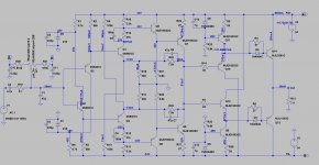
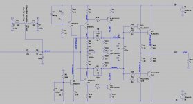
1. One has a diamond buffer output stage with a single transistor pair and no degeneration.
2. Two has a classic emitter follower with 0.22ohm emitter resistors and two parallel pairs.
Below are the circuits exactly as built. One runs the output transistors at 260mA and two runs the parallel pair at 100mA ea. I realise this is not exactly the same, should have run the parallel pair a bit hotter but the particular heatsink did not leave me confident as i wanted to test up to 250W.
The simulations show almost exactly the same distortion numbers as the real things.
Attachments
I'm familiar with the circuit... Obviously it's 90% output stage distortion even at low power levels. This amp should be easy to experiment with different feedback amounts.. With one resistor added you could include output stage in feedback loop too and try for instance, does it sounds better with only 6dB feedback around output stage... I bet it does 😊
- Home
- Amplifiers
- Solid State
- Dartzeel amp schematic - build this?