The reason for this is that CPLD reclocks the signals in order to eliminate the jitter added by the isolator. Adding isolator after reclocking would make no sense.Somehow for 300 pages is missing that the JL sounds does have digital ISO, BUT only from XMOS module to CPLD module.

yes, has someone said the opposite ? Stop the flys last outrages please 😉 ! trust your ears !
@bohrok2610 I compared the PCM1704 with and without isolator directly ... it sounds better without the isolator ... idk what was affected 🤣
Which isolator was that? Many isolators have quite high jitter which may well be the cause for audible differences.
Question for you fellows, what sort of DC current offset have you encountered with the AD1862?
Do you agree with the datasheet spec? (Midscale Output Error max ±5 μA)
Thanks,
Alex
Do you agree with the datasheet spec? (Midscale Output Error max ±5 μA)
Thanks,
Alex
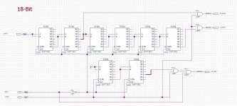
Stop Clock 2 for DAC AD1862 - PCB
Stop clock 2 for AD1862 #2832 - untested 😀
If someone confirms that it works, I will create a DAC PCB with this logic.
Miro, have you any experiment with Stop Clock 2 for DAC AD1865 and with all 18 bit DAC? I have seen 20 bit conv for AD1862 and 24 bit conv for TDA1541 here.
Can you draw a correct circuit for one 18 bit AD1865 or two AD1865? Thank you very much.
@TokRa This Stop Clock 2 for AD1862 is still untested (but I think it does work).
You can move 2 wires in the schematic to make it work with the AD1865 😉 (but as I told, I am not sure if it is bit perfect, because I did not check it with real digital analyzer, it is only simulated ... in case of an error, those bits would only be shifted by +-1 with those wires).
You can move 2 wires in the schematic to make it work with the AD1865 😉 (but as I told, I am not sure if it is bit perfect, because I did not check it with real digital analyzer, it is only simulated ... in case of an error, those bits would only be shifted by +-1 with those wires).
Attachments

Looking at the datasheets they seem to be pin compatible, but the AD1864 has a +5V and -5V supply for the digital part, while the AD1865 only has +5V for the digital part.
@Myint67 Maybe yes 🤔
Measure voltages between pins:
1 and 5 (gnd)
24 and 5 (gnd)
9 and 13 (gnd)
... if the voltage on those pins is +5V or -5V then you can insert the AD1865 directly with lifted pin 16 (this pin 16 is not connected on the AD1865!) ... if the voltage is higher, then you can't insert it directly ...
But why do you need to change the AD1864? It is very good chip.
Hello . I would like to build this DAC, but I don't know what parts to buy and how to order the PCB boards. Is there a list somewhere with each piece? Please be patient and understanding with me because I don't know how to do projects of this kind, but I could stick parts on a board. 🙂
I found this . Some parts are out of stock .Mouser BOM/Project links
Hope this is OK to share and helpful for those really new to this. Some parts are on back order due to global supply chain issues for electronics. You can use Mouser's search feature to find identical products in some instances.
If anyone sees any errors/omissions then please let me know and I will update.
DAC PCB v1.3 #1351 - excludes the AD1862 chips and the pin headers (assumes you will solder cables to the board). Based on socketed/DIL8 LM6171 opamps,
https://www.mouser.com/ProjectManager/ProjectDetail.aspx?AccessID=ce95e68314
PSU1 #1460 - excludes a suitable transformer, otherwise fully populates the board with screw terminal headers for power in/out
https://www.mouser.com/ProjectManager/ProjectDetail.aspx?AccessID=60a068042e
SPDIF/Optical to I2S #2249 - excludes the 3.3v optical reciever - try TORX147, not stocked by mouser, check eBay/AliExpress
https://www.mouser.com/ProjectManager/ProjectDetail.aspx?AccessID=8d6ea97f46
I2S Input Selector #2526 - assumes on board tactile switch and LEDs, if remote then you can remove item 1 and 2 from the BOM
https://www.mouser.com/ProjectManager/ProjectDetail.aspx?AccessID=8c09689ace
There is even simplier, ask someone to sold you a populated one !
But the ad1862 themselves you have to purchase in a group buy on the eponym diyaudio section, all the parts can be swapped by others brands equivalents but the shift registers.
Eventually you do not need the shift registers if printing the board that can be stacked with the USB to I2S from JLSOUNDS Lab. Read the thread.
Last edited:
Sticking parts on a board?….…..because I don't know how to do projects of this kind, but I could stick parts on a board. 🙂
Have you successfully soldered and built any projects?
I am not aware of a glue with metal powder in it that could replace the soldering process... contacts need to be good in order electron flow without restriction (local resistances)
Perhaps start with a couple of simpler projects (complete kits?) where there are fewer unknowns for you so that you can gain some experience and build up some confidence over time.@zoom777 I read it but it's too complicated for a novice. I was thinking of something simpler like a project or list sharing on DigiKey.
Or watch for a forsale of a built unit?
- Home
- Source & Line
- Digital Line Level
- DAC AD1862: Almost THT, I2S input, NOS, R-2R