@miro, I have had a closer look at THS4031's data sheet and have seen that its 2nd harmonic distortion is relatively high, even with a low value 300R feedback resistor that it is optimized for. I also haven't heard any success stories with this opamp as a dac IV. I am quite hesitant about placing an order just for them. I wonder why you recommend trying them? Thank you.
The OPA1611A, though theoretically should measure the best, does not measure as well in this dac.
Did you try running OPA1611 on +-11v rails? Bypass it with the same film caps diyiggy uses for clocks? Change the value of the integrating cap across the feedback resistor? If not all those things and more, how are you going to learn what works?
@Hidy It has higher output current and 4x higher the slew rate (suitable factor in I/V). One guy in this thread recommended it. Internal diagram is identical with AD797 and is 2-3x cheaper as AD797.
I have experience with THS3001 (the best transparency I have ever heard ... different internal diagram - CFA), but it needs cooling (SMD pad from the bottom) 🙂
I have experience with THS3001 (the best transparency I have ever heard ... different internal diagram - CFA), but it needs cooling (SMD pad from the bottom) 🙂
Last edited:
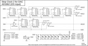
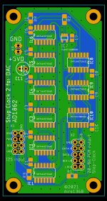
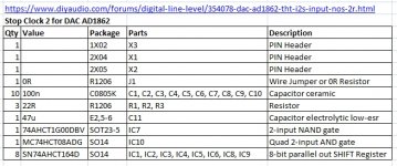
Stop Clock 2 for DAC AD1862 - PCB
Stop clock 2 for AD1862 #2832 - untested 😀
If someone confirms that it works, I will create a DAC PCB with this logic.
Stop clock 2 for AD1862 #2832 - untested 😀
If someone confirms that it works, I will create a DAC PCB with this logic.
Attachments
Did you try running OPA1611 on +-11v rails? Bypass it with the same film caps diyiggy uses for clocks? Change the value of the integrating cap across the feedback resistor? If not all those things and more, how are you going to learn what works?
@Markw4, I measured opa1611 with this setup: +-12v power bypassed with 0.1uf kemet polypropylene film caps, a 82pf polystyrene cap plus a 100R 0.1% Vishay Dale +-10ppm moisture resistant metal film resistor across a Takman 3K Ohm 0.25W REY feedback resistor.
I wonder which film caps diyiggy has used for clocks, can you be more specific?
Last edited:
I wonder which film caps diyiggy has used for clocks, can you be more specific?
IIRC there were some SMD film Rubycon in values up to .22uf, and Cornell-Doublier .1uf (available from Digikey). SMD is sometimes better than leaded components when low ESL matters. If any ringing on the power pins is observed then a small SMD resistor may be needed in series with a film or C0G cap for damping. At least the film caps are pretty linear (same for higher voltage version of C0G/NPO). In parallel with the small caps I would probably add some 10uf electrolytics or tantalums. The latter can be pretty nonlinear, but sometimes they work anyway. Good, reliable electrolytics include Panasonic FM and or FC. Its not necessary and not always better to use caps labeled by the manufacturer for use in audio applications. I still see people peppering famous-name audio caps around without doing any checking to make sure they are really the best choice.
Regarding OPA1611, may I ask how you are measuring distortion coming out of the opamps? Reason I ask is there is can still be a lot of RF and clock noise at the output of an IV opamp. That junk can cause distortion in downstream devices which might be more the problem.
The idea of the cap across the IV feedback resistor is to start filtering out RF noise and to take some of the load off the IV opamp at RF frequencies. Some trial and error may be needed to search for the best value. Also, in IV circuits any capacitance to ground before the opamp inverting input can cause frequency peaking and or instability. That said, some filtering of RF before the IV opamp can be be helpful if kept to minimum. Adding resistors in series is bad because it increases distortion, so any pre-filtering has to be on the mild side. It can still help though. Another thing to consider is that a lot of radiated RF may be measurable very close the the dac chip and or close to clock and I2S signal lines. Best to keep the IV opamp from coupling with those fields. Ground and power rail currents coupled with noise sources can also be problematic. Thoughtful layout and careful experiments may be needed to get things right.
EDIT: When experimenting with caps, I leave some time for burn-in before judging caps in a particular circuit. Electrolytics tend to settle most but not all of of the way overnight. Some large high quality film caps can take a week or more to 'open-up' in the low midrange where the ear tends to be sensitive so it can be good to allow for some patience.
Last edited:
IIRC there were some SMD film Rubycon in values up to .22uf, and Cornell-Doublier .1uf (available from Digikey).
Regarding OPA1611, may I ask how you are measuring distortion coming out of the opamps?Thank you Markw4 for your detailed explanations. Much appreciated🙂
Regarding the SMD Rubycon and Cornell-Doublier caps, it seemed that you were referring to Acrylic Metallized caps. If so, do you think this will sound better than 0.1uf pp films:
Digikey part number: FCA0805C104M-J2
0.1 µF Film Capacitor 12V 16V Acrylic, Metallized 0805 (2012 Metric)
I measured opa1611 by just connecting the rca line out of my miro ad1862 dac to the rca line in of my Creative X-Fi Titanium HD sound card. The whole link is like this: PC usb out -> usb cable -> Xmos isolated USB I2S -> miro ad1862 line out -> rca interconnect -> creative x-fi Titanium HD line in - > PC
...do you think this will sound better than 0.1uf pp films:
Digikey part number: FCA0805C104M-J2
0.1 µF Film Capacitor 12V 16V Acrylic, Metallized 0805 (2012 Metric)
Don't know, sometimes the only way to find out is to do the experiment. Of course with such caps I would be very careful about staying within the voltage ratings.
I measured opa1611 by just connecting the rca line out of my miro ad1862 dac to the rca line in of my Creative X-Fi Titanium HD sound card. The whole link is like this: PC usb out -> usb cable -> Xmos isolated USB I2S -> miro ad1862 line out -> rca interconnect -> creative x-fi Titanium HD line in - > PC
My concern would be that RF noise passing through the IV stage might cause distortion in your sound card. It can help a lot to have a scope and maybe a network analyzer or spectrum analyzer to look at what is coming out of the IV. I would probably add some additional passive filtering and buffering before going into a measurement system.
I did confirm with a 60Mhz oscilloscope that there were no RF noises or oscillations at all. The signals were actually quite clean, with a measured THD of 0.0031%. This was pretty good. Only the AD797 and ss3601 were able to go even lower with this dac, to as low as 0.00271%.
What does the distortion spectrum look like for different opamps?
IMHO, THD is considered a fairly useless metric for design and development. Its mostly used for test in manufacturing because it is a quick and easy way to test for consistency between units.
Regarding the distortion spectrum, very low order harmonics are not very objectionable to most humans. Higher order harmonics sound worse, sometimes much worse. Therefore weighting schemes have been suggested as an improved metric better correlating with sound quality. Hard to get people to use newer metrics though. Guess they are resistant to change...
http://www.gedlee.com/Papers/THD_.pdf
EDIT: Also, do you have scope shots of the output? What probing technique was used? 10x probe? Ground spring?
Good info on scope probes and grounding of probes in: https://download.tek.com/document/02_ABCs-of-Probes-Primer.pdf
Grounding discussion is near the end starting around page 46.
Last edited:
At Hidy,
That is an interesting job that you do here.
How are made the measyremment please ? Are all the oap tested just swapped on a DIL8 header ?
I am curious to know the best practice of local decoupling on le soic oap legs when they are soldered on SOIC to DIL ? Values of the cap (0.01 uF on the legs if the Dil 8 pcb has already 0,1 uF decoupling on the pcb?) , which cap and on which legs?
Are the measurements benchmark valid if not made on the soic oap pcb from the V1.3?
Also for the op861, I know nothing about measurement but I guess as there is no local feedback it should sound better but measure worse? Rogic uses it as he was using the previous transconductance oaps: no feedback. IMO the best is to use Vunce op861pcb adapter with just the first I/V stage w/o the second buffer stage for proper benchmark.
I don't know if we really care about thd...all that oaps have very low Thd and I am not sure the difference you can check with your ears are just about thd. In my experience, each might need a different choice of passive parts around as different values with R & C to push each at their best sonic result...and it is depending of what you have after in your hifi. What sounds good in your hifi when tweaked at best, oap choice, decoupling, powering, passive part choice, differ in relation of each hifi you have and the also the oap you use.
Rogic is using said bad carbon comp in serie with the op861 and not a dead silent metal film. Some distorsion spectra can be pleasant (300B tube, etc).
If I use indeed FCA caps, it is not always.
All those modern oaps are all good....op810, 1611, 1602, 1656, op861, 1648 (Abraxalito prefer it to the 1612 iirc)non limited list....as say Miro, hard to test them all and judge them as the also drive the load and not used as pure I/V task.
0805 smds are easy to soldering (with glasses & flux !)
I have VERY few to share on a technical point of view but for the gerber drawers, when good sound and tweaking are still in the party, something Veryyyyy cool (but it's cool enough imho already) could be something like that after the two ad1862 to give even more tweaking/Diy room:
For the AD1862 and oaps very near decoupling :
- mkp 5 mm pitch swaped for 0805 smd trace for FCA caps in 0805 casing 0.1 uF circa. trace till the vias and the smd pad even shorter than actual pcb. Eventually vias on the pads and the trace for ones whom prefer 5 mm MKP (blue Ero -which has a sligthy warmer sound than the other 5 mm pitch MKPs, Wima or Kemet).
But not sure it's a good practice to ad vias on power rail trace for decoupling, I don't remember what the TI wiki papers said about this ???
- Of course still the low pitch width areas for lythic caps as already there in the pcbs. (A-PSA polymer caps with the blue top marking are quite cool for the AD1862 and a solid alternatice for the Pan FR for the digital side; has to be tested for the 12V rail though with listening sessions benchmark.
-A little like the headphone pcb from Miro but simplier : a first I/V soic area inspired from Rogic shematic Vunce adapted in a DIL8 board. This first Soic area would have the same decoupling smd pads to use imho the PSA caps with 0.1 uF to 1 or 2 uF. +/-5V rails than be coupled
-with a second soic area for the buffer/filter stage with your prefered 5V oap according the load you need, 1656, LMxxxx, op16xx for headphones. If possible and if the I/V symetry permits it, the buffer oap should be chose with the range of minimal offset that avoid DC coupling cap- while there should be room for the lythics DC blocker if needed/wanted. The serie coupling between the two stage can be made with a Sussumu 0805 resistor case size. Instead a seond soic for the buffer two smd transistors low noise - see EUVL for all the good advices for modern reference or what remplace the NLA SK170- ?
Miro's board already have jumpers for the ones wanting refinment with multiples power stages.
- the last important thing is imho to give more size room for the I/V resistor to acomodate Bulk or little longer resistors.
Since the V 1.3 non soic, there has also the uf-l input version which is handy for the one streaming from a Fifo Pi or an I2S to PCM (IanCanada board) or the stacking version for the JLSounds (I will keep the good NDK-A in lieu). I think perhaps the IanCanada which has several data and LRCK outputs can already drive the AD1862 in both I2S or simultaneous mode ??? IanCanada can certainly answer. But know that the I2S to PCM board has some logics to be used with othr IanCanada gears only (that's a commercial lego stacking): the Fifo Pi is ok I beleive as it has a Master clock output the I2S to PCM board is needing. For the one needing only USB, the JLSounds is your better bet.
A last detail could be to put the decoupling trace of the 4.7 uF cap on the bottom of the pcb right in the bottom od the AD1862 legs to make the path shorter : imagination is the limit : smd pads for FCA caps, or 3.5 pitch as already for the lythic Pan FR or FC cap.
I also know some have used a double diode in reverse each other position to protect the AD1862 output if my memory serves me well.
Of course an discrete I/V could be made direct onthe pcb, but as say Rogic paper already about the AD844 : sorting out transistors is not for all and oaps are symetric enough. I surmise the opa 861 to be good enough and matched enough.
A pity someone is not working on Miro's gerbers, cause Miro's hands deserve well earned holydays imo 😀 🙂 , Btw I'm sorry I can't , but this can give to some the envy, will it be better ? I'm *F******K* don't know, just sharing my little modest experiments/tweaks!
Last edited:
Stop clock 2 for AD1862 #2832 - untested 😀
If someone confirms that it works, I will create a DAC PCB with this logic.
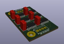
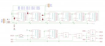
I don't have the parts for the stopped clock logic, but I have a populated gluelogic board which can be used to test the stopped clock circuit:
Here is the schematic:
The upper part is on the PCB, the lower part is Miros additional circuit: just wire it together with my pcb as shown and it should be possible to see if everything works. If anybody wants to do this I am happy to provide the pcb. I would be particularly interested to see if both channels benefit from stopped clock as timing seems to be slightly different!
Attachments
Well, as an option, you can use one of the best DF SM5847, I don't know how many there are in VCAMERICA, but you can buy it and the price is not terrible.
You can use DF based on this project, like a non-commercial
Documentation attached
Inserting Zero samples is a bad solution. The right solution for oversampling is to use the Sinc function. If you want the digital oversampling filter to sound nice and refined it must use Sinc (LPF) function instead of inserting zero samples in its algorithm.
Doesn't zero stuffing followed by infinitely sharp cutoff linear phase LPF effectively converge to the same result as sinc? IIUC either way it takes an infinitely long filter to do it perfectly. So the question always becomes how good is good enough? According to Chord it takes an incredibly long filter to do it well enough to be inaudible. On the other hand, well implemented AK4137 ASRC chips could do a quite credible job of upsampling with what must have been far simpler calculations than Chord's optional prescaler boxes use.
I don't understand the discussion about stopped clock and glue logic procedures but I would be interested in building up different variants.
on a different note:
I just received a run of PCB's from JLC and could mail them at cost to the continental United States. Packs would include one PSU board (v1 or 2) + jlsounds NOT flipped 1.3 board + post filter board. Send me a PM if you'd like a set
on a different note:
I just received a run of PCB's from JLC and could mail them at cost to the continental United States. Packs would include one PSU board (v1 or 2) + jlsounds NOT flipped 1.3 board + post filter board. Send me a PM if you'd like a set
What does the distortion spectrum look like for different opamps?
EDIT: Also, do you have scope shots of the output? What probing technique was used? 10x probe? Ground spring?
Thank you Markw4. That's quite some information to learn.
I didn't notice any drastic differences in the distortion spectrums of different opamps. They all look quite clean except for the harmonics. Here is an example.

My experience is that THD measurement is a very effective way to catch any ringing or oscillations, that have an effect on the audio band, without a scope. Whenever my opamps run into oscillations, the THD measurements go wild.
This was how I probed the dac with my scope: first, I connected the dac line out to my headphone amp line in, then I paralleled my scope probes to the same dac out put, probe to positive output, ground to output ground. I set probe to 1x to be more accurate.
I didn't take a scopeshot because I didn't see anything interesting or weird. There were just +-8mv voltages noises when the dac was on standby. There were no regular waves or patterns of oscillation. Once the dac started playing, the voltage started to jump up and down, with a peek to peek voltage of 3V with a 1k5 feedback resistor, which looked quite normal.
At Hidy,
That is an interesting job that you do here.
How are made the measyremment please ? Are all the oap tested just swapped on a DIL8 header ?
I am curious to know the best practice of local decoupling on le soic oap legs when they are soldered on SOIC to DIL ? Values of the cap (0.01 uF on the legs if the Dil 8 pcb has already 0,1 uF decoupling on the pcb?) , which cap and on which legs?
Are the measurements benchmark valid if not made on the soic oap pcb from the V1.3?
@diyiggy Yes, all my soic opamps are installed on soic to dip8 adapters for easy swapping.
One could safely assume that soic opamps will perform at least as well if not better when put on v1.3 soic pcb. Still, the measurements did with adapters are valid in a sense that they would indicate how the dac performs in a worst case senario.
And, based on measurements with adapters, 0.01uf caps are not needed because the opamps are working fine without them. The 0.1uf decoupling caps on the pcb are good enough. I tend to believe that a 1uf will also work, because I do have another ad1862 dac bypassed with 1uf caps that is working well, although I only tested it with ears and with RMAA. One day I will verify this with my scope.
If you would like to add 0.01uf caps right at the opamp legs, you can put one cap across pins 7 and 3 to decouple +12V, and another cap across pins 3 and 4 to decouple -12V.
Cheers🙂
I didn't notice any drastic differences in the distortion spectrums of different opamps. They all look quite clean except for the harmonics. Here is an example.
Those harmonics look quite audible, to me at least. That's a problem then. A lot of the spurs could simply be related to insufficient filtering of a zero-order-hold dac output. May take some work to figure out and fix all the underlying causes.
Sometimes people will choose not to filter a dac output because they don't like the filtered sound. To me it means there is something wrong somewhere, maybe multiple things. Could be there is a problem with filter implementation. Could be other problems are making the dac sound muffled and the distortion is sort of helping to cut through the mud to produce a sound that seems more balanced and clear. Hard to say for sure without hearing it on good, very low distortion speakers (electrostats). Short of having reference grade speakers, a good headphone amp and good headphones can help make it easier to hear what is really going on with the sound of an audio device.
Guess I will say here the same as sometimes advised to others: it may be worth building your own Pass HPA-1, since there is a forum thread on it with a schematic attached to one of the posts. Stereophile uses it as their reference HPA to compare the sound of all headphones in reviews. There is no better HPA for that purpose at this time, at least not that I know of. One thing to be aware of is that HPA-1 is not the same as Whammy. Two very different designs.
Once one has reference grade reproduction equipment then tracking down and fixing problems in dac designs by ear becomes much more practical. IMHO distortion measurements are good too, but they don't tell the whole story about SQ. For example, clock jitter can affect SQ but it tends to look like noise on an FFT. May or may not sound like noise to a human though, again this is just IMHO.
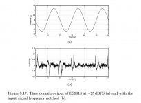
EDIT: Regarding looking at dac distortion with a scope, unless the distortion is really severe it will be hard to see on a scope. The way to see it in the time domain is to use a notch filter and some makeup gain after the filter to show a "notched-out time-domain filter-residual." Example pic attached below.
Attachments
Last edited:
Thanks Hidy for the feedback.
Hmm, I am wondering if the rank would change on the soic pcb version...
Decoupling...same conclusion as you...and truer with modern regchip. Sometimes I finf 1 to 2 uF to sufice. Gives a certain room to choose caps model and voice accordingctje oap and personal tastes. I don t use the 47 uF with the modern regs. I also do not like too much paraleling more than 10 uF near the load if 0.1 uF is also there.
- Home
- Source & Line
- Digital Line Level
- DAC AD1862: Almost THT, I2S input, NOS, R-2R