@Markw4
In my opinion one can build a very good headphones amplifier from this EUVL design.
A Simple Discrete Current-Mirror IV Converter, à la AD844
In my opinion one can build a very good headphones amplifier from this EUVL design.
A Simple Discrete Current-Mirror IV Converter, à la AD844
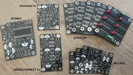
I checked my parts bin and found some left over PCBs from my modular DAC project which could be handy for testing purposes - if anybody is interested drop me a PM. For testing the stopped clock circuit the PCBs for AD1862 and the gluelogic DIP version (one is populated) would be useful as mentioned in this post. The circuits are very similar if not identical to Miros. Also I have iv-stages with opamps and the discrete diamond, each one PCB. And finally PCBs for PCM63. All PCBs are tested and working.
Attachments
@Markw4
In my opinion one can build a very good headphones amplifier from this EUVL design.
There is a lot to like about that circuit. Doesn't quite look like a fully designed HPA to me though. If it was turned into a complete HPA then it might be interesting to A/B compare with some other good ones. Without listening its hard to reach a final opinion. The HPA I suggested is one I have heard, and its one with multiple reviews and awards. It would probably be a good one to compare with.
Last edited:
@Markw4
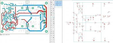
A few days ago I designed testing PCB of this HPA-1 for my friend who has good ears listened to various other devices. Without solid GND plane, but if the basic will sound good, then I will improve it. I wonder what he will say
A few days ago I designed testing PCB of this HPA-1 for my friend who has good ears listened to various other devices. Without solid GND plane, but if the basic will sound good, then I will improve it. I wonder what he will say
Attachments
Last edited:
Oh, no doubt it can be improved. I would only suggest to build the original design first in order to make sure any mods really are improvements in SQ, not just improvements in measurements. You know what I mean, I think.
EDIT: The original power supply is an important part of the sound, of course. The transformer quality matters too. Suggest Toroidy Audio Grade with a bit more current rating than you need.
EDIT: The original power supply is an important part of the sound, of course. The transformer quality matters too. Suggest Toroidy Audio Grade with a bit more current rating than you need.
Last edited:
@Markw4
I think the PSU will be done in the near future 🙂
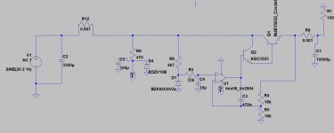
What do you think about this PSU? I created simple LM358 based PSU with an emitter folower stage, which is stable for any capacitance load.
Maybe I would create something from discrete parts with this stage, but I don't know any good schematic or design 🙁
I think the PSU will be done in the near future 🙂
What do you think about this PSU? I created simple LM358 based PSU with an emitter folower stage, which is stable for any capacitance load.
Maybe I would create something from discrete parts with this stage, but I don't know any good schematic or design 🙁
Attachments
The HPA-1 schematic includes the power supply. I think I can post the version here from the thread. For any electrolytic caps I think Panasonic FM might be fine where the needed values are available. They take some time to fully burn-in, but transient response is hard to beat once they do. It is suggested to build the original power supply before trying different mods.
Attachments
Last edited:
It is nice PSU with capacitance multiplier on the output. I will do a few simulations and build something 🙂
The power supply should not be too loose, nor too tight in regulation. John Curl told me it needs to dance with the music, if it makes any sense to speak in such language. I think John meant he thinks moderate regulation sounds better for some circuits.
Miro, why not to try to supress the resistor between the base and the output and not to stay for a simple ref or zener stack at the base. Sim will be worse but what about the dynamic ? I would supess the last big resistor for something closer to 0,5 to 2 uF but film cap and divide the first 3300 cap by two of 1200 I can give the reference if you decide to test that way. I like a lot that topology and sometimes we just don't care about better thd number or ultimate stability.
My two cents.
My two cents.
Hi,
Works for both, fast and low impedance output. Choice of parts are critical. Audial that makes very musical dacs uses simplified such tipology witj discrete parts and one darlington .
Works for both, fast and low impedance output. Choice of parts are critical. Audial that makes very musical dacs uses simplified such tipology witj discrete parts and one darlington .
Um... If building HPA-1, it may be best to build it according to the original design first, let it burn-in for at least two weeks, then get used to the sound. At that point might be a good time to do some modding experiments to see if it can be made to sound 'better.' I already know some improvement is possible, but I'm under NDA. Sorry. If someone does figure out how to make it better in A/B tests in particular, then other builders might interested to try it as well. The difficulty of course is not fooling one's self in listening tests. Could be something to talk about more if anyone gets to the point of A/B experimenting on the original design.
What is the method of not fooling oneself in listening test? Please share.The difficulty of course is not fooling one's self in listening tests.
Thanks iggy and Mark. I was referring to psus for the dac chip in Miros pcb and also maybe the mirror discrete IV. I have some nice small psus, unregulated as such but healthy capacitance MX. Might try them.
Evenharmonics ....do you just follow Mark and try to wind him up?
Evenharmonics ....do you just follow Mark and try to wind him up?
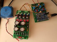
AD1862, I2SoverUSB v.III - not flipped, 20-Bit uf.l connectors
meanie, and others,
I was not able to open your image referenced in the Title and in post #2682, in the format posted in the thread . I think these type of formats become non-responsive after time.
I would really like to see what it looks like, as I may want to venture down this avenue myself.
Meanie, could you post another pic of your setup, or anyone having a pic of meanies setup?
Thanks,
MM
@Jim04, Think maybe he is being paid off by his business associates to stalk, harass, and conspiracy theorize?

meanie thanks, that is useful for those of us closer to the front end of the learning curve.
Even though the JLS board is attached to the miro board, it looks like we still need to prep that with jumpers as it details in the user manual. Is that correct?
If I understand correctly that's why you've got the jumper on J4 on the top of your USB/I2S board?
Even though the JLS board is attached to the miro board, it looks like we still need to prep that with jumpers as it details in the user manual. Is that correct?
If I understand correctly that's why you've got the jumper on J4 on the top of your USB/I2S board?
- Home
- Source & Line
- Digital Line Level
- DAC AD1862: Almost THT, I2S input, NOS, R-2R