Yes, it is good to go thru the JLsound manual for proper config for the AD1862 chip.
I jumpered on the JLsound board because J1-4 was not connected to Miro's (not flipped)board.
I jumpered on the JLsound board because J1-4 was not connected to Miro's (not flipped)board.
Hi meanie,
Could you repost these also. Sorry to be a pain!!
27th October 2021, 04:43 AM #2521
Click the image to open in full size.
Click the image to open in full size.
Click the image to open in full size.
Click the image to open in full size.
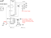
For those using JLsound direct without registers, here is my configuration.
Last edited by meanie; 27th October 2021 at 04:46 AM.
Could you repost these also. Sorry to be a pain!!
27th October 2021, 04:43 AM #2521
Click the image to open in full size.
Click the image to open in full size.
Click the image to open in full size.
Click the image to open in full size.
For those using JLsound direct without registers, here is my configuration.
Last edited by meanie; 27th October 2021 at 04:46 AM.
Has anyone built and implemented the filter? Interested to hear about subjective impressions and/or measurements!
Also I'm reading about sallen key filters (like here: https://www.electronics-tutorials.ws/filter/sallen-key-filter.html)
Miro, in #2738 you gave 3 options for sallen key filters. If I understand correctly, two of these are set up for unity gain and config 1 has a gain factor of 1.6. I understand that cf = cutoff frequency, but what do Qf and Df mean? can you give us a quick description of what these three configurations might look and sound like in application?
I am guessing that config 1 will suppress ultrasonic imaging the most but with the most noticeable HF rolloff approaching 20khz, while config 3 might have a more natural rolloff in the audible frequencies but allow more +20khz artifacts?
Hi meanie,
Could you repost these also. Sorry to be a pain!!
27th October 2021, 04:43 AM #2521
@Kokanee,
I checked the post #2521 pictures are still working fine.
Pm me if you still need them.
Thanks meanie, I went back into the thread and yes they were there. I usually download pics from the "enhanced print view" and insert them into a word doc for later use ( since I am new and very slow in building). The ones in the "epw", were just 4 blocks, so I could not open them, hence I copied from the actual thread. No worries.
MM
MM
@asilker
Higher Qf means that fewer unwanted frequency signals will pass through, but it can affect the sound more significantly, that is why 0.7 is considered as golden ratio.
Df is harder to explain, but read it here: Electronic devices: Active Filters [part 1] ... you can experiment with values, because what will sound better is hard to say 😀
@tistvan2
You are correct, what a mistake 😀 Thank you for warning.
Pin 8 of IC4 can be lifted and connected to the GND with 10k resistor and R3 will be shorted.
Here is the corrected PCB.
You are correct, what a mistake 😀 Thank you for warning.
Pin 8 of IC4 can be lifted and connected to the GND with 10k resistor and R3 will be shorted.
Here is the corrected PCB.
Attachments

Last edited:
Maybe you can answer how to not fool one self in listening tests?Evenharmonics ....do you just follow Mark and try to wind him up?

@Evenharmonics
How can the brain identify a hundred ns jitter in recordings?
How we distinguish between a good melody and a disturbed melody?
Wow can we even hear the noise in the recording?
What noise but also distortion and also say that this recording is authentic and this one is not? 😀
How can the brain identify a hundred ns jitter in recordings?
How we distinguish between a good melody and a disturbed melody?
Wow can we even hear the noise in the recording?
What noise but also distortion and also say that this recording is authentic and this one is not? 😀
Regarding the I/V opa, I see Iggy and plenty of other fine folks discussing options and I think I will be trying the ADA4627 opa's first.
Question: The ADA4627 comes with suffix options ARZ/BRZ, [none]/R7/RL. I can't figure out what these suffixes mean by looking at the datasheets. It looks like the biggest distinction between A-B is the voltage input offset between 70uv and 120 uv. Which suffix of this op amp do I want?
Also it appears that none of the fresh new op amps are produced in DIP8 packages. Is it industry standard that all the new stuff is SOIC and smaller?
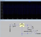
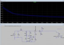
The power supply should not be too loose, nor too tight in regulation. John Curl told me it needs to dance with the music, if it makes any sense to speak in such language. I think John meant he thinks moderate regulation sounds better for some circuits.
Under 120mA pulse load it has some voltage dance.
In comparison the 7812 regulator under the same load is pretty clean 😀
Attachments
@asilker A = Average, B = Better ... you are fine with the cheapest because you will test another opamps as well, there is not enough opamps 😀
Still no help on how to conduct listening tests so that you don't fool yourself. Markw4, diyiggy, miro1360 or anyone?
Ask for help someone experienced. It works just like when you don't have the skills to repair a car, you can ask someone you know he has the experience.
... or you can learn the experience, it takes time - and of course fooling yourself is necessary during the learning process 🙂
... or you can learn the experience, it takes time - and of course fooling yourself is necessary during the learning process 🙂
Last edited:
- Home
- Source & Line
- Digital Line Level
- DAC AD1862: Almost THT, I2S input, NOS, R-2R