
More output current? and on paper , improvement in the THD since bit weight errors is reduced. Not sure if this means I can hear better sound. If i do not like it, i unstack and i try to sell them again. I am trying because i have the chips in my hands now and as you know, MOQ 5 for the boards....
Fantastic Zoom! Glad your build was successful and your enjoying the end result 😁.
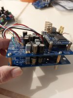
The board was designed so the current inputs will be directly above or below (depends on positioning) the MiroDac output headers so connections can be as short as possible. Keep that in mind for your proper chassis build.
This started as a personal project and was never meant to be released out in the wild. But after I built and listened to this paired with MiroDac AD1862 I figured a few of you would like to build it also. Grunf and W.Jung deserve all the credit for the foundation of this shunt regulator/AD811 board, I just personalized it 😉.
ENJOY!!
Last edited:
zoom,
Nice. It inspired me to troubleshoot the power supply on my board.
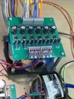
I was able to get the negative side operational. I'm getting about 9.7mV from the negative and positive of the shunt, but the voltages on are not.
The negative is good at 11.75v, but the positive is 17.5v. What should be my first step to troubleshoot my voltage issue.
I did installed a couple of 180ohm 3w resistors. One from TP405 to ground and the other from TP407 to ground. Also the Q403 and Q411 get real hot.
Nice. It inspired me to troubleshoot the power supply on my board.
I was able to get the negative side operational. I'm getting about 9.7mV from the negative and positive of the shunt, but the voltages on are not.
The negative is good at 11.75v, but the positive is 17.5v. What should be my first step to troubleshoot my voltage issue.
I did installed a couple of 180ohm 3w resistors. One from TP405 to ground and the other from TP407 to ground. Also the Q403 and Q411 get real hot.
AD811 has a much worse power supply rejection than classic op amps, so the quality of the regulator itself is important, a super regulator can be used to replace the shunt regulator.Question: How much different would Vunce's 811 I/V topology sound if used with a more conventional power supply, assuming good filtering and supply cap values, rather than the Jung/Grunf supply. Is it an incremental difference or a huge difference? Objective opinions please if you have them, not confirmation bias. Thanks.
you must have a short circuit somewhere, do the LEDs light up?zoom,
Nice. It inspired me to troubleshoot the power supply on my board.
I was able to get the negative side operational. I'm getting about 9.7mV from the negative and positive of the shunt, but the voltages on are not.
The negative is good at 11.75v, but the positive is 17.5v. What should be my first step to troubleshoot my voltage issue.
I did installed a couple of 180ohm 3w resistors. One from TP405 to ground and the other from TP407 to ground. Also the Q403 and Q411 get real hot.
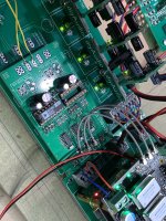
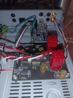
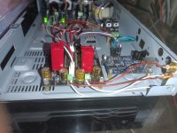
I'm glad you're satisfied with the sound of the AD811, it's a forgotten gem that is unfortunately rarely used today in audio.I would think this is the last op amp IC IV stage I would try on my AD1862. I tried Opa1655 , Lme49680, opa2604 using dual to single adaptor board and single op amp like opa604, Ad844 dual stacked, Ad797, ada4267, and lately Opa627. Vunce's IV using AD811 is staying with the Dac. In terms of resolution, may not be as good as Opa627 but the AD811 sounds warm, full bodied especially in the mids and the bass is tight and goes deep. Thanks @Vunce
*Pardon the messy set-up. It is for a test run and will eventually case the Dac.
Last edited:
Thank you for sharing generously to enable the IV to be built.I'm glad you're satisfied with the sound of the AD811, it's a forgotten gem that is unfortunately rarely used today in audio.
This is such a beautiful instrument. It looks too serious to be just for music!💪Listening to my AD1862 Quick Mock up build. With Pedja Rogic’s discrete IV stage 👌
Hi, guys. A few month ago @John Burson wrote to me with offer totake on test his opamps. Of course I said yes, because it's a great opportunity to listen a new discrete opamps from Burson Audio! And the other days I got two new one-channel opamps (V6 Vivid). I was thinking to change in AD1862 but there is a no place for them (they are big) and I changed Opa604 on AD 1865. I was wondering how they'd do the new discretes. after a little work I've started to listening the music. Of course I compared them to 604.
V6 Vivid have more details, separation and wide stage on full display. Sound is warm with a good texture and rich vocal. Very impressive microdynamics and attention to details. Also bass is more extended and rounder. I like acoustic guitar and vocal. There's a lot of different artists for example Allan Taylor and Ian Bruce. Their guitars have become more transparent, natural and fuller.
I didn't realize there could be such a difference between opamps! I'd like to hear in conjunction with the AD1862 but I need to think how to install them.
And my real photos with opamps!
Attachments
Thank you for the response. I have not had a chance to check. I will get to it later today. I did not populate the I/V stage yet. I wanted to make sure the power supply was working properly.what are the voltages at PVref, op amp output, current through Q411 (voltage drop at R403)?
If there is anyone who is interested in a free AD811 IV board:
https://www.diyaudio.com/community/threads/free-ad811-iv-boards.404613/#post-7486611
https://www.diyaudio.com/community/threads/free-ad811-iv-boards.404613/#post-7486611
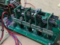
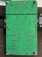
Hello @Vunce , what format is that unzipped BOM file? How do I read a .numbers or other file included here? Thanks.After a few revisions and a couple weeks of the Grunf/Jung inspired shunt regulator AD811 IV board working very well paired with my AD1862 MiroDac its time to share it with you Fellas. If you are interested, I would recommend reading through Grunf's thread for: ad811-as-i-v-stage-for-current-dacs-and-test-some-other-op-amps-including-burson-audio-op-amps-as-i-v.394295
- A 30VA transformer with two 18V secondaries wired in series or center tapped 18V-0-18V is required to power the board.
- Heatsinking is required for Q403, 404, 410 and 411.
- Built with the listed BOM components: 105mA shunt current per rail, +/-11.55V for AD811 opamp.
- Mounting holes are the same spacing as DAC board to stack input header above and close to DAC Iout.
I tried to make it as easy as possible to build, but it does use several SMD components, Don't be scared.
Huge thank-you to Grunf and jhofland for all the help and support!!
Contact me by PM and I'll send you the Gerbers for this project.

- Home
- Source & Line
- Digital Line Level
- DAC AD1862: Almost THT, I2S input, NOS, R-2R