G.Kleinschmidt said:
Do you have some kind of fixation with me?
You following me?? Is that your hot breath on my neck? 😉
G.Kleinschmidt said:
No
LOL
I've searched for the upraised middle finger smiley, but failed to locate it.
Use your imagination.
vynuhl.addict said:Hi All,
I decided to try and implement a few of the ideas presented here. I found the earlier comment on the Widlar 3bjt mirror being profoundly superior sonically to the 1n4148 connected mirror bb-c, my sonic findings were quite the opposite as the 3 bjt Widlar seems far from musical, this was tied to the rail from the connected bases with a 680r resistor for 1.1ma of draw, C was connected to ground. Compared to the diode the sonics became very forward, bright and with Bass that somehow seemed a little disconnected from the rest of the party happening would be the best to describe, at first it will strike as superior but gives that incisive razor sharp edge that feels more like an aural lobotomy. The 1n4148 seems consistent top to bottom with a more relaxed silkier sound, very sweet top to bottom with deep. powerful and non bloated low end, soundstaging I find superior overall although its not immediately apparent and takes some listening to pinpoint the subtleties. I did not try the more complex ideas layed out here but must say, between the two the small signal diode connected mirror to my ears is the clear winner no contest, regardless on linearity in sims...
Colin
My results were very different but then again my VAS only draws 0.0012mA which is exactly offset by the helper transistor. Depending on your VAS current gain and quiescent current the 3 transistor Widlar may well result in a degraded performance. You can't simply look at the mirror in isolation.
VHF man said:
My results were very different but then again my VAS only draws 0.0012mA which is exactly offset by the helper transistor. Depending on your VAS current gain and quiescent current the 3 transistor Widlar may well result in a degraded performance. You can't simply look at the mirror in isolation.
Just from a technical POV if the "helper" transistor is the same type of transistor as used for the VAS buffer (same Hfe) the base currents drawn from each LTP leg will offset if the emitter resistors are selected for the same standing current in both transistors. I presume this is what you've done.
However several uA imbalance in a LTP running a decent tail current of a few mA certainly isn't going to be an issue.
Cheers,
Glen
CM Discussion
"By help do you mean saying something that is at odds to what I believe? I have a problem believing there is an audible difference with any mirror (or none for that matter). I hold this view, therefore my help is not wanted."
Colin
You mentioned in a previous reply that you used an emitter follower as well, and the values of your CM resistors were much lower.Subjectivity didn't come into my response. I made no mention of very close matching in that reply. I did point out that the circuit as it stood ,appeared to be far from optimum in this particular application. In particular,only 400mV across the input side CM transistor, where use of the more usual 68-100 ohm resistors may have been more appropiate. There would appear to have been a much greater potential for a closer match of the LTP currents, without resorting to tricks such as I described elsewhere.Surely that would be good engineering practice ?
Higher values of CM resistor appear to be mainly used to cover up gross errors in the CM ? At least, that is my limited understanding of the subject, as gleaned from the books by D.S. and other magazine designs. BTW, several Sydney based
DIYAudio members, and a U.K. member have heard my efforts, and there are currently a couple being constucted in the U.K. as well. I just don't post that much here because of the unpleasant sniping by some members. (I am not referring to you here.)
I know of several other DIYAudio members who refuse to get involved for the same reason.
Alex
Re: CM Discussion
I'm not entirely sure if you are talking to me or Colin.😕
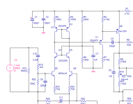
To clear up, the schematic I posted while "discussing" things with Glen is Ostrippers amp, with the third transistor added to the existing mirror. The way that OS illustrates in another schematic on his thread would not work in simulation.
For reference, the pertinent parts of mine is below.
Sorry if i came in a little strong. I was responding to something I may have imagined in your post.
sandyK said:
I did point out that the circuit as it stood ,appeared to be far from optimum in this particular application. In particular,only 400mV across the input side CM transistor, where use of the more usual 68-100 ohm resistors may have been more appropiate. There would appear to have been a much greater potential for a closer match of the LTP currents, without resorting to tricks such as I described elsewhere.Surely that would be good engineering practice ?
Higher values of CM resistor appear to be mainly used to cover up gross errors in the CM ? At least, that is my limited understanding of the subject, as gleaned from the books by D.S. and other magazine designs. BTW, several Sydney based
DIYAudio members, and a U.K. member have heard my efforts, and there are currently a couple being constucted in the U.K. as well. I just don't post that much here because of the unpleasant sniping by some members. (I am not referring to you here.)
I know of several other DIYAudio members who refuse to get involved for the same reason.
Alex
I'm not entirely sure if you are talking to me or Colin.😕
To clear up, the schematic I posted while "discussing" things with Glen is Ostrippers amp, with the third transistor added to the existing mirror. The way that OS illustrates in another schematic on his thread would not work in simulation.
For reference, the pertinent parts of mine is below.
Sorry if i came in a little strong. I was responding to something I may have imagined in your post.
Attachments
CM discussion
John
Sorry, it was meant for you. I was thinking about Hugh's reply at the time.
Alex
John
Sorry, it was meant for you. I was thinking about Hugh's reply at the time.
Alex
MJL21193 said:
You following me?? Is that your hot breath on my neck? 😉
I've searched for the upraised middle finger smiley, but failed to locate it.
Use your imagination.
you guys and your current mirrors😀 😀


G.Kleinschmidt said:
Just from a technical POV if the "helper" transistor is the same type of transistor as used for the VAS buffer (same Hfe) the base currents drawn from each LTP leg will offset if the emitter resistors are selected for the same standing current in both transistors. I presume this is what you've done.
However several uA imbalance in a LTP running a decent tail current of a few mA certainly isn't going to be an issue.
Cheers,
Glen
Yes, this was the way I implemented it For a lower beta VAS the helper's emitter resistor should of course be made smaller. Obviously it helps to know the hfe of each device and the magnitude of VAS and LTP currents.
The helper transistor collector current is set by the vbe of the current mirror control device + the voltage developed across its emitter resistor.
I agree though that a few uA one way or the other is not an issue but if you know the hfe of each device then it's pretty easy to select the closest 5% resistor value to get the LTP currents very closely balanced. You might also want to balance the current mirror collector voltages by some manipulation of VAS emitter resistance and / or VAS quiescent current. It stands to reason that the current mirror devices will track better if their operating conditions are made equal (ie. both VCE and IC), particularly if you've gone to the trouble of matching them for hFE at the selected operating current.
Whether you consider going to such lenghts to be really beneficial is another issue but there do seem to be a number of people looking for the perfect mirror. For myself, perfect mirrors are something I've stopped looking into.
Cheers,
VM
Iain McNeill said:
you guys and your current mirrors😀 😀
Yes, with all this mirror talk we are creating a poor reflection of ourselves in the DIY community. 🙁 😱
By MJL -To clear up, the schematic I posted while "discussing" things with Glen is Ostrippers amp, with the third transistor added to the existing mirror. The way that OS illustrates in another schematic on his thread would not work in simulation.
It did work, but "squirrely" .The CM emitters are better at
under 220R (eliminated my offset bias "window" as well).
I've am playing with LTspice (thanks again to lineup)🙂
and am able to approximate any changes "before the fact"
eliminating the stress of possible real world failure.
As far as failure goes , I'm surprised I haven't burnt one
single tranny. I even have enough left over to build 1
more amp!! with all these cool ideas I think a VAS/OP/CCS
board with a plugin SMD "daughter card" for the
input stage is in order..
OS
Re: CM Discussion
Hello Alex
I fully agree with you, few months ago we chat by email about a
closer match of the LTP currents, I did try few versions of LTP currents matching, with and without CM, in every case there was good gains in the sonic quality, with a much better definitions and soundstage.
Better is to do a very close match of the LTP currents before doing a complicated CM, and as VHF say "You can't simply look at the mirror in isolation" . LTP, CM, and VAS are like the three musketeer they work as a team.
Where is the good in making an amp for the best sim and measurements if it does not sound better !
Bye
Gaetan
sandyK said:
... There would appear to have been a much greater potential for a closer match of the LTP currents, without resorting to tricks such as I described elsewhere.Surely that would be good engineering practice ?
Higher values of CM resistor appear to be mainly used to cover up gross errors in the CM ? At least, that is my limited understanding of the subject, as gleaned from the books by D.S. and other magazine designs. BTW, several Sydney based
DIYAudio members, and a U.K. member have heard my efforts, and there are currently a couple being constucted in the U.K. as well. I just don't post that much here because of the unpleasant sniping by some members. (I am not referring to you here.)
I know of several other DIYAudio members who refuse to get involved for the same reason.
Alex
Hello Alex
I fully agree with you, few months ago we chat by email about a
closer match of the LTP currents, I did try few versions of LTP currents matching, with and without CM, in every case there was good gains in the sonic quality, with a much better definitions and soundstage.
Better is to do a very close match of the LTP currents before doing a complicated CM, and as VHF say "You can't simply look at the mirror in isolation" . LTP, CM, and VAS are like the three musketeer they work as a team.
Where is the good in making an amp for the best sim and measurements if it does not sound better !
Bye
Gaetan
AKSA said:Colin, Alex,
Great info, many thanks.
I think what is NOT obvious is the disconnect between simmed THD figures and subjective assessment.
Time and again the two appear out of step. All this agonizing over 0.005% distortion figures seems faintly ridiculous vis a vis the 5% THD of a really good single ended triode....... there's something more to this than meets the eye, or 'ear'.
I think there is far too much priestly class breast beating around here..... never have so many unmusical amplifiers been designed by so few for so many with such fanfare.
I tried the diode too and thought it was great. No short term reverse biasing, either, it all went very predictably.
Hugh
Hello Hugh
Amusing to see that this CM thread start to become, as many other theads, to about two sides; the numbers vs the ears ways of amps makings...
I am far from having the knowledge of most guys in this thread, but the chat I ad with you give me a boost and resurrected my amps works. A plain ordinary amp topology become a living and musical sounding amp. The result are there, you design amps by using your ears and it's working.
Btw, last year at the Montreal audio show, one of the best sounding amp was a tube amp, and even a friend who was moking tubes topology did ear this difference and living 3d sound from this tube amp. Distortion figures are far from showing everything about an amp.
Bye
Gaetan
Hi Gaetan,
This is the eternal squabble between the two camps; math/measure v. golden ear, left v. right brain.
Neither side is interested in the others arguments; each thinks the other side is stupid, belief ridden, unobjective, rigid, inflexible, etc, the list goes on.
During these furious debates there is a large number of potential customers out there wanting a truly musical amplifier, willing to pay money, and enjoy their music.
21193 showed there was no THD difference between the diode trick on a CM and the short; yet, we can hear it. This should ring alarm bells.... but then, being uncomfortable with something which cannot be objectively explained is patently not the way the math/measure approach works. More research required.
Off to the Melbourne Audio Club tonight, should be a pleasant evening, watching the two camps eyeing each other off......
Hugh
FIrst off, to Sandy K, the emitter resistors of the CM were 47R and using the bjt in repacement of the diode there should be no additional mods as thiis transistor will effectively function as more or less an active diode with a similar v drop to a small signal diode, roughly .7v. The Ltp was matched very evenly, dc offset of .06mv precisely per channel so the playing field was even for both setups. I firmly believe both camps play a huge role in design , subjectivist vs objectivist as both have qualites that often each party ultimately desires, but really go hand in hand, now if they can all just agree to disagree we could really design some stellar gear, Linux for audio??, haha. Ultimately it is the ears that are the judge, potential buyers really dont give two hoots about measurement but yearn for the experience and joy of music, low distortion is good, but it really depends on the tradeoff to acheive this goal, sometime alike music its more intuitive than measurable..
Colin
Colin
Re: Re: CM Discussion
Hi Gaetan,
I have no reason to doubt the audible differences you report, but that doesn't say much about the preferred current mirror topology. Your test was done in some sort of amp (I assume), of which we have no info, with a certain way of building it, certain power supply, certain grounding scheme and another zillion factors involved.
If I do the same test in MY amp, I may have the exact opposite result. Or no difference at all. That is the difficulty with such an anecdotal test: it may make perfect sense to *you*, but that's about all you can say.
Jan Didden
gaetan8888 said:
Hello Alex
I fully agree with you, few months ago we chat by email about a
closer match of the LTP currents, I did try few versions of LTP currents matching, with and without CM, in every case there was good gains in the sonic quality, with a much better definitions and soundstage.
Better is to do a very close match of the LTP currents before doing a complicated CM, and as VHF say "You can't simply look at the mirror in isolation" . LTP, CM, and VAS are like the three musketeer they work as a team.
Where is the good in making an amp for the best sim and measurements if it does not sound better !
Bye
Gaetan
Hi Gaetan,
I have no reason to doubt the audible differences you report, but that doesn't say much about the preferred current mirror topology. Your test was done in some sort of amp (I assume), of which we have no info, with a certain way of building it, certain power supply, certain grounding scheme and another zillion factors involved.
If I do the same test in MY amp, I may have the exact opposite result. Or no difference at all. That is the difficulty with such an anecdotal test: it may make perfect sense to *you*, but that's about all you can say.
Jan Didden
You who use and prefer current mirrors, how would you describe the sonic improvents vs. using resistors? Or were your choice using CM other than improving the sound like lower offset, better measured performance or higher CLG?
CM Discussion
vynuhl.addict
Did you check the voltage difference between the collectors of the LTP ?
I know that it seems improbable what I suggested originally, however there have now been quite a few amplifiers and preamplifiers constructed in Sydney, as well as one of each in the U.K., using the balancing methods previously supplied.
There are more than 5 other DIY Audio members who have listened to such modified amplifiers and preamplifiers. 3 members have balanced the front end of their amplifiers and CLass A preamplifiers, either using the added diode to the CM, as described, in conjunction with trimming the difference voltage between the LTP collectors, or using the series Schottky diode and trimpot in the unloaded side of the CM. Halcro patented the additional diode concept in 1999. Which is some time after we started using that method. Halcro amplifiers are renowned for their 3D soundstage.
Incidentally, the Silicon Chip Class A amplifiers that were modified were quoted by Silicon Chip magazine as having a typical THD of .0006%. These amplifiers have far better matching of devices and resistors than the original designs.
SandyK
Hi,
current mirrors in many applications have a sonically destructive effect, not related to accuracy, which in the first place should be discussed and solved.
Also, in my view, several examples found in application notes are not suitable for audio (regardless price).
current mirrors in many applications have a sonically destructive effect, not related to accuracy, which in the first place should be discussed and solved.
Also, in my view, several examples found in application notes are not suitable for audio (regardless price).
- Home
- Amplifiers
- Solid State
- Current Mirror Discussion