jam said:syn08.
You seem to be one of those meter men.😉
1. Your assumption is all types of distortion sound the same.
2. The distribution or harmoinc content might be different.
3, I have tried it why don't you. Several other members seem to concur, including Glen. There are fundamental problems with the two transistor mirror, Mr.Google might help you here.
Is this an excersise in if you can't measure it , you can't hear it or are you more interested in displaying your credentials. So I leave it up to you to prove me wrong
I suggest you build a circuit and graft in the changes and prove it to yourself.
Warmest regards, (and I mean it)
Jam
1. No, I don't. Who said that?
2. And your point is? What has this to do with the topic?
3. Set aside the fact you know **** about what I've tried and what not, care to share your methodology and results?
The endless discussion: you are making a statement and others are supposed to prove you are wrong. Sorry, but it doesn't work this way.
All you wanted to know about current mirrore but were afraid to ask.
Here is a bit more reading for those inclined..........
http://books.google.com/books?id=1F...X&oi=book_result&resnum=7&ct=result#PPA239,M1
homodder,
You may find page 273 of some intrest as it talks about the patent circuit.
Regards,
Jam
P.S. After all this I need to take a nap.
Here is a bit more reading for those inclined..........
http://books.google.com/books?id=1F...X&oi=book_result&resnum=7&ct=result#PPA239,M1
homodder,
You may find page 273 of some intrest as it talks about the patent circuit.
Regards,
Jam
P.S. After all this I need to take a nap.
Jam, no offense meant, but there are many here that have Toumazou et al's book on their bookshelf. For much longer than a decade.
Jan Didden
Jan Didden
Hi Jan,
No offence taken. I had discoverd it a few years ago myself. My intention was to help anyone that had not seen it and point out the analysis of one of the Wilson varients as described in the patent (lowering the peaking in the ac response), besides what about the nubies? 😉
But honestly I am fairly green myself an have nowhere the credentials of some of the members here.
Best regards,
Jam
syn08,
Sorry you feel that way. I guess you have use what works best for you. (You amp schematics show your choice and if it works use it)
Regards,
Jam
Sorry you feel that way. I guess you have use what works best for you. (You amp schematics show your choice and if it works use it)
Regards,
Jam
jam said:Hi Jan,
No offence taken. I had discoverd it a few years ago myself. My intention was to help anyone that had not seen it and point out the analysis of one of the Wilson varients as described in the patent (lowering the peaking in the ac response), besides what about the nubies? 😉
But honestly I am fairly green myself an have nowhere the credentials of some of the members here.
Best regards,
Jam
You are a gentleman.
Jan Didden
jam said:lineup,
The Nakamura seems worth investigating (maybe homemodder would be kind enough to run a sim for us) the others are just over the top.
I would like to thank you , homemodder and the rest of the members that have kept this thread alive with your valuable insight.
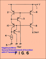
Nagamura looks very promising, jam.
Why?
Because both 'mirror-transistors' Q2-Q6 has got 2xVbe across CE.
this makes it like 1.2-1.3 Vce.
And no matter what the output point voltage, this stays the same.
Here is the test I am going to do.
I will use same 1 mA, modulated +-100uA 10000 Hertz test, as with 'Glen' and 'Jam' mirrors.
See my test setup Post #152
http://www.diyaudio.com/forums/showthread.php?postid=1659653#post1659653
But as Nagamura needs more than 1.3Volt output I will set the output voltage ar 2.0 Volt
I will retest and compare with my 10 kHz signal, using my usual 15 harmonics Fourier.
Be back with my Glen/Jam/Nagamura results soon.
________________________
Note & disclamier.
My mirror test setup, is an attempt to isolate only mirror performance.
It is a bit as to show only HFE diagram of one Transistor in a datasheet.
When Transistor is put into a circuit, there is no ideal test situation.
The context in what the mirror is to be used matters.
But we can get a hint 'how good' a transistor is, compared to other Tansistors from datasheets using same test setup.
Same way, we can get a hint about 'how good' different Mirrors are, in comparison.
The potential they have, if the context, circuit they work in is right.
Attachments
On the subject of current amps, does anybody have any of these documents:
Negundadi, A, "A dual differential dual current converter", Proc of the IEEE, 1980, Vol 68, pages 932-934;
or
Negundadi, A, "High-current Class-AB converter technique" Electron Letters, 1980, 16, Vol 68, pages 418 and 419.
Much obliged!
Jan Didden
Negundadi, A, "A dual differential dual current converter", Proc of the IEEE, 1980, Vol 68, pages 932-934;
or
Negundadi, A, "High-current Class-AB converter technique" Electron Letters, 1980, 16, Vol 68, pages 418 and 419.
Much obliged!
Jan Didden
lineup said:
Nagamura looks very promising, jam.
Why?
Because both 'mirror-transistors' Q2-Q6 has got 2xVbe across CE.
this makes it like 1.2-1.3 Vce.
And no matter what the output point voltage, this stays the same.
Here is the test I am going to do.
I will use same 1 mA, modulated +-100uA 10000 Hertz test, as with 'Glen' and 'Jam' mirrors.
See my test setup Post #152
http://www.diyaudio.com/forums/showthread.php?postid=1659653#post1659653
But as Nagamura needs more than 1.3Volt output I will set the output voltage ar 2.0 Volt
I will retest and compare with my 10 kHz signal, using my usual 15 harmonics Fourier.
Be back with my Glen/Jam/Nagamura results soon.
________________________
Note & disclamier.
My mirror test setup, is an attempt to isolate only mirror performance.
It is a bit as to show only HFE diagram of one Transistor in a datasheet.
When Transistor is put into a circuit, there is no ideal test situation.
The context in what the mirror is to be used matters.
But we can get a hint 'how good' a transistor is, compared to other Tansistors from datasheets using same test setup.
Same way, we can get a hint about 'how good' different Mirrors are, in comparison.
The potential they have, if the context, circuit they work in is right.
The Nagamura current mirror is also attractive because it provides a built-in way of biasing the output cascode without incurring the problem of the nonlinear collector-base capacitance feeding its current back to the input side of the current mirror. Secondly, the currents on both sides pass through a cascode transistor, so both currents suffer the same alpha loss if the transistors are matched in beta.
Notice, however, that both of the "helper" transistors should have some current pulled from their emitters for best performance (rather than relying solely on the base current of the transistors they are driving). This is especially true of the lower helper transistor, as it is exposed to output cascode transistor base currents developed by high slew rates across the cascode's collector base capacitance.
Cheers,
Bob
andy_c said:And by "competent design" I don't mean an early 1970s HK Citation clone that some hack treats like it's his intellectual property.
😀
homemodder said:MJL21193 werent you also trying this and that to address issues you had with your amp and evaluating cons and pros, same is happening here on this thread. Its not about the perfect current mirror in so much, but how it affects the surrounding circuitry. Maybe you think its futile, same some members though it futile for you achieve lower THD or better squarewave response but this was important in your view while not shared by everyone else. Perfection doesnt exist in electronics and I doubt in anything else. No need to come critisize people here for evaluating current mirrors rather contribute something usefull or share your thoughts even if its that you think it futile but then say so and state your reasons and put them up for scrutiny.
Hi homemodder,
I did make some comments early on, but was dismissed out of hand as an amateur. I don't mean to offend, just playing around a bit, looking for attention.
THD and squarewave response are telling features of an amps accuracy, if I'm not mistaken, so these are worth paying attention to in my book. I am more obsessed with stability than anything else and most of my efforts went there.
Knowing as little as I do, I do find it very hard to believe that there will be an audible difference between one mirror and another. It's my opinion that there is sometimes too much attention paid to these very minute details.
The quest for technical perfection is noble, and good; to do these changes to an actual circuit with the idea that the difference will be heard is an interesting exercise, for sure.
I wish you luck! 🙂
Bob Cordell said:
Notice, however, that both of the "helper" transistors should have some current pulled from their emitters for best performance (rather than relying solely on the base current of the transistors they are driving). This is especially true of the lower helper transistor, as it is exposed to output cascode transistor base currents developed by high slew rates across the cascode's collector base capacitance.
Cheers,
Bob
Isn’t that so with the buffered Widlar as well? (3 transistor Widlar)
For best performance the emitter of the “helper” transistor would need some sort of current sink.
Regards
Stinius
Hi All,
I have been enjoying the Current Mirror debates greatly but very silently. But not being able to keep still too long I decided to try and implement a few of the ideas presented here. I found the earlier comment on the Widlar 3bjt mirror being profoundly superior sonically to the 1n4148 connected mirror bb-c, my sonic findings were quite the opposite as the 3 bjt Widlar seems far from musical, this was tied to the rail from the connected bases with a 680r resistor for 1.1ma of draw, C was connected to ground. Compared to the diode the sonics became very forward, bright and with Bass that somehow seemed a little disconnected from the rest of the party happening would be the best to describe, at first it will strike as superior but gives that incisive razor sharp edge that feels more like an aural lobotomy. The 1n4148 seems consistent top to bottom with a more relaxed silkier sound, very sweet top to bottom with deep. powerful and non bloated low end, soundstaging I find superior overall although its not immediately apparent and takes some listening to pinpoint the subtleties. I did not try the more complex ideas layed out here but must say, between the two the small signal diode connected mirror to my ears is the clear winner no contest, regardless on linearity in sims...
Colin
CM Discussion
Colin
Please see my recent post in the "Frugalamp " thread.
It appears that the "experts" with their simulators, are missing the obvious.
SandyK
Colin
Please see my recent post in the "Frugalamp " thread.
It appears that the "experts" with their simulators, are missing the obvious.
SandyK
Obvious.
Here's what I like to do here. I amuse myself from time to time by having a look at some of the previous posts of a person who I find "interesting". One can gain insight into the kind of person he is and what he is interested in. You might even see an example of the fine DIY effort the person has made - a speaker or a chip amp or some such. Something to admire or say "hey, this guy is not full of hot air like I first assumed, but a member to be reckoned with".
Sometimes, this isn't the case.
Colin, Alex,
Great info, many thanks.
I think what is NOT obvious is the disconnect between simmed THD figures and subjective assessment.
Time and again the two appear out of step. All this agonizing over 0.005% distortion figures seems faintly ridiculous vis a vis the 5% THD of a really good single ended triode....... there's something more to this than meets the eye, or 'ear'.
I think there is far too much priestly class breast beating around here..... never have so many unmusical amplifiers been designed by so few for so many with such fanfare.
I tried the diode too and thought it was great. No short term reverse biasing, either, it all went very predictably.
Hugh
CM Discussion
MJL21193
You missed the obvious by not showing that you were using an emitter follower in your recently posted schematic. You didn't explain that either.As I said how about trying to be helpful instead of spoiling other peoples thread's by teasing Glen. What has any of that got to do with the thread from Ostripper?
SandyK
Hi Hugh,
I"m not hung up on THD figures although less is generally better for a solid state amp if I understand correctly. Limits exist, I know and anything less than .05% is a probably a wasted effort.
The purpose of the simulation, which was lost on everyone, even Glen, was to show that there wasn't a recognizable difference. I could not see a difference in balancing in the LTP here either. This is what the extra transistor is supposed to address, right?
Interestingly, the diode solution, first proposed by you, doesn't effect THD in my sim. It also doesn't have any notable effect of current and voltage thru the LTP in the sim.
Re: CM Discussion
Hi Sandy,
There are a couple of threads devoted to my schematic. It's not hard to find.
By help do you mean saying something that is at odds to what I believe? I have a problem believing there is an audible difference with any mirror (or none for that matter). I hold this view, therefore my help is not wanted.
Glen is up to his usual "look at me" tricks again. I don't mind if a mod cuts all of that out and either tosses it or puts it where it belongs (here).
At worst, it was good publicity for OS's thread 🙂
sandyK said:MJL21193
You missed the obvious by not showing that you were using an emitter follower in your recently posted schematic. You didn't explain that either.As I said how about trying to be helpful instead of spoiling other peoples thread's by teasing Glen. What has any of that got to do with the thread from Ostripper?
SandyK
Hi Sandy,
There are a couple of threads devoted to my schematic. It's not hard to find.
By help do you mean saying something that is at odds to what I believe? I have a problem believing there is an audible difference with any mirror (or none for that matter). I hold this view, therefore my help is not wanted.
Glen is up to his usual "look at me" tricks again. I don't mind if a mod cuts all of that out and either tosses it or puts it where it belongs (here).
At worst, it was good publicity for OS's thread 🙂
MJL21193 said:The purpose of the simulation, which was lost on everyone, even Glen, was to show that there wasn't a recognizable difference.
Do you have some kind of fixation with me? I have repeatedly stated that the improved mirror will have a neglible effect and called it a pointless modification in a typical amp. And I certainly don't buy the subjectivist evaluations.
What is under dispute is your dodgy claim that the improved mirror will worsen the performance. If your sims show otherwise, then they are screwed up somewhere.
MJL21193 said:I could not see a difference in balancing in the LTP here either. This is what the extra transistor is supposed to address, right?[/B]
No
LOL
Re: Re: CM Discussion
Talk about a case of projection.
MJL21193 said:Glen is up to his usual "look at me" tricks again. I don't mind if a mod cuts all of that out and either tosses it or puts it where it belongs (here).
At worst, it was good publicity for OS's thread 🙂
Talk about a case of projection.
- Home
- Amplifiers
- Solid State
- Current Mirror Discussion