Hi jpatay,
I see that your new PCB layout has just the single cap (C1) at the input. Would you mind testing with unbalanced input again to see if this improved square wave symmetry?
I see that your new PCB layout has just the single cap (C1) at the input. Would you mind testing with unbalanced input again to see if this improved square wave symmetry?
In my early designs I just used 0.1 - 0.47 uF across each transformer secondary, and even that made an improvement.
Tomorrow I will install capacitors.
Hi jpatay,
I see that your new PCB layout has just the single cap (C1) at the input. Would you mind testing with unbalanced input again to see if this improved square wave symmetry?
What frequency to watch? What capacity to put C1?
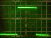
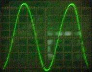
Thank you jpatay. I don't see any real improvement in symmetry, but perhaps distortion in the audio range will still be good enough for use with unbalanced inputs. We'll see.
I don't see any real improvement in symmetry,
This is the fault of the oscilloscope. I did not establish symmetry on the oscilloscope.
Ah OK, thanks for the clarification. What is the peak voltage at clipping? It should be 1-2 volts less than the supply - maybe 33-34V?
The second time to bring to clipping failed. Blown IRF1010E and fuse.What is the peak voltage at clipping?
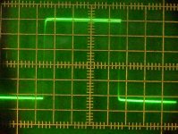
Before clipping, I saw excitation on an oscilloscope. The amplitude is 15 V. The load is 8.2 Ohm.
Replaced IRF1010E, it became bad. The amplifier was excited under load. Replaced C3, C4 - 39 p, C5, C6 - 150 p. It did not help.
Installed 30 Ohm in Gate IRF1010 and it got better. Tomorrow I will increase to 100 Ohm.
Seb,test your amplifiers for excitement. Maybe this is so bad only in my amplifier.
Last edited:
The second time to bring to clipping failed. Blown IRF1010E and fuse.
In this design, the Vds across each output device can reach 70V (twice the supply voltage) on peaks. The IRF1010E data sheet shows possible Vds breakdown as low as 60V, so that may have been the problem.
In this design, the Vds across each output device can reach 70V (twice the supply voltage) on peaks. The IRF1010E data sheet shows possible Vds breakdown as low as 60V, so that may have been the problem.
I agree, but with the increase in power, excitement still appears.
I will look for it.
Can they be protected from this without compromising the design?
The simplest protection from Vds breakdown is to use output devices with a Vds rating higher than twice the supply voltage, as in the original design. If there's some additional problem here, it can be addressed separately.
I see, yes of course can't avoid that Vds at clipping. Just not the right devices for the rail voltage. I know MOSFETs aren't keen on overvoltage.The simplest protection from Vds breakdown is to use output devices with a Vds rating higher than twice the supply voltage, as in the original design. If there's some additional problem here, it can be addressed separately.
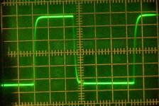
When the current increases by more than 150 mA, the amplifier is excited.
I installed a Zobel filter (10 Ohms + 0.1 μF) and the excitation disappeared.
I installed a Zobel filter (10 Ohms + 0.1 μF) and the excitation disappeared.
Reduced the supply voltage to 28 V.
Reduced the resistors R17,18,19,20 to 270 Ohm.
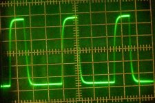
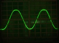
Clipping starts at 25 V. One division on the oscilloscope is 5 V. The load resistance is 9 ohms.
RMS power - 25x25 / 9 = 69.5 W. Correctly?
It is also necessary to reduce the resistors R8, R9.
P.S. Now IRF1010E can work.
Reduced the resistors R17,18,19,20 to 270 Ohm.
Clipping starts at 25 V. One division on the oscilloscope is 5 V. The load resistance is 9 ohms.
RMS power - 25x25 / 9 = 69.5 W. Correctly?
It is also necessary to reduce the resistors R8, R9.
P.S. Now IRF1010E can work.
Attachments
Last edited:
r.m.s. power is 50% of peak power, so 25 x 25 / 9 / 2 = 35W
Or put another way r.m.s. power = Vrms^2/R = (Vpeak/√2)^2/R
Or put another way r.m.s. power = Vrms^2/R = (Vpeak/√2)^2/R
- Home
- Amplifiers
- Solid State
- Current feedback Mosfet Circlotron