@ e_fortier:
36 volt rail may give about 21 Vrms out, or ~55 watt in 8 ohms. Peak current is then ~3,6 A.
For 4 ohms, rails probably will drop a bit, so say 20 Vrms out means ~7 Apk, or ~5 Arms and 100 watt.
It may be on the higher side, but they are rough devices so with good cooling it may work.
And there's a difference in listening and pushing it to maximum, so try it !
/Figge
Anyone?
I guess I’ll just build and hopefully my Exicon won’t blow up in Silicon smoke...
Based on the previous amp, my bias will be set to 500mA
BR
Eric
Eric,
I use a +/- 36V power supply with my Cubie3 and have the bias set to 500ma. Case is a Dissapante 2U/300 with 0.45 C°/W heatsinks. These heatsinks do get quite warm but not excessively hot. Output transistors are the now extinct 2sj162/2sk1058.
Speaker load is 4 ohm. No silicon smoke - just really good sound.
WoW, exact same setup as mine, that really confirms everything. Thanks a lot for the detailed answer.
Happy Canada Day !
Eric
Happy Canada Day !
Eric
I need help, please!
Hi,
I need some help setting the Cubie3 offset. I must say, first, that all my transistors except the output Exicons (ECX10N20 and 10P20) are matched, the complementary ones and the ones in each of the mirrors.
First, I shunted the inputs to the ground and set the output offset to ''0'' volts. Then, I took off the shunt but no input connection and noticed that the offset is now about 30 mV to one channel and about 60 mv to other...and I've set again the offset to ''0''. The sound is much, much better now with the second setting.
Could you explain to me why this is happening and which one setting to apply, as a general rule? Is there a general rule for shorting or not the inputs when setting the offset or...it depend on input transistors topology? Please, enlighten me..
Thanks in advance for the answer!
The sound is much, much better now
Very strange. Have never noticed such insignificant offset to be audible at all, but all my speakers are of average sensitivity.
You should really set the offset under normal operating conditions. The input will be grounded through the preamp's output resistor if the preamp is ac coupled or will see the preamp's dc offset if it is dc coupled. In the case of a TVC/AVC - through the winding resistance.
Many thanks for the quick answer and advice! I have very sensitive ears so I can hear ''hidden'' details like this tiny offset. When not settled to zero, there is a veil, the sound is closed-in. At zero offset, the sound open-up, the veil is removed and the details are revealed. That's what I hear, even the difference in sound is very small.
I'll follow your advice, thanks!
Out of curiosity: what speakers do you use? I would imagine high sensitivity, wide range single drivers would be a lot more sensitive to dc offset.
I'm sure the ones you've mentioned are even more sensitive to the offset than mines. I own a pair of Dick Olsher's Poly Natalia DIY Loudspeakers made by myself and founded for sale on eBay right now as a kit. The sensitivity is around 92-93 db. Maybe the Audax medium driver HM130-Z0 Aerogel cone ( 600 to 4000 Hz) and the Morel ET 338 are responsible for the detailed sound.
About the Cubie 3 Amp I must say I love it ! Better than JLH 20W or Hiraga - both ''Le Monstre" and 20W that I own and will be on sale because of this one!
Juma, you are a great designer! Thank you for this lovely amp!
About the Cubie 3 Amp I must say I love it ! Better than JLH 20W or Hiraga - both ''Le Monstre" and 20W that I own and will be on sale because of this one!
Juma, you are a great designer! Thank you for this lovely amp!
Does someone have a pair of PC boards and one PS board?
For a fair price. Please PM me.
Otherwise, I may try to produce my own homebrew, I will not order 10Pc or so from China from each. I am not in that position.
Homebrew not the same quality and not very inspiring to install quality components to DIY with homebrew boards. I did it before!
Many years ago I built a clone of the ProFet amp, I would love to replace that amp with this. Thanks!
Hi Juma,
Thanks for sharing this design! Based on the success of my DIY HPA-1 (with a similar topology), I was thinking of building a Cubie3 in an Aleph O-style case.
I adjusted a few things to use the KSA/KSC parts I have on hand and to bump the rail voltages up a bit. I had to lower the current through the Vbe, and adjust the cascode bases a bit. I also lowered the gain slightly, but I'm not sure if this was because it was just too high for me to start with, or if my changes above increased it.
Since I'll have gobs of heatsink, I also upped the bias to the zero-temp-co value (800mA). The laterals probably deserve chunky copper heat-spreaders under them to get the heat out to the whole heatsink (each one will have its own side of the case).
Anyway, I don't think I did anything stupid, but I'm pretty new at the analog side of things so I could well have. One thing I did notice is that it goes into oscillation when over-driven (ie: 1.4V at the input). The unmodified schematic does this too, so maybe it's just my SPICE models or something?
Any comments appreciated.
Thanks,
Jeff.
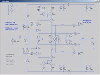
Attachments
Hello Jeff,
2SK and 2SJ are rated for 100W only. Do plan to make multiple output device for 140W-4ohms?
regards
Prasi
2SK and 2SJ are rated for 100W only. Do plan to make multiple output device for 140W-4ohms?
regards
Prasi
Hi Prasi,
As I understand it paralleling output devices would require source resistors, and the lack of source resistors is likely a big factor in Cubie3's sound.
Note that 100W is at a Tc of 25ºC. Running at a more reasonable Tc of 60º derates them to about 70W. Note that we're well into class B here so we get to add two 70W to give us 140W.
Running them there continuously would no doubt give a rather unsatisfactory device lifetime. But music doesn't look like a sine wave, and I only need the 140W for transients; average will probably be closer to the class A envelope numbers (10 - 20W).
But they will be on flying leads, so they'll be easy enough to replace. 😉
Cheers,
Jeff.
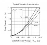
Sometimes you don't need source resistors if paralleling output devices. If you look at the old Halfler DH 220 it used a pair lightly matched of parallel 2sk135 , 2sj50 lateral mosfets I believe these devices were rated at 125v and have a negative tempiture coeficent above 100 ma I believe this would help ballence curents. And while the 2sj62 also has a negative temperature coeficent it doesn't come into play till the bias is above 600ma per device.
Adding a second pair of output devices hugely improves the class A performance. I lowered the bias to 700mA (for a 32W idle dissipation) and got 60W into 8ohms and 30W into 4 (with class B headroom of 160W).
Shouldn't need the copper heat-spreaders in this config (lower output per device and output spread over heatsink with more devices).
Shouldn't need the copper heat-spreaders in this config (lower output per device and output spread over heatsink with more devices).
THat is strange I would have sworn I saw a graph showing the negative coefecent didn't kick in till 600 ma but your graph shure shows I was wrong.
Another question: Juma indicates a max Vbe current of 4-5mA. What determines the sweet spot for this? (In other words, *why* a max of 4-5mA?)
And do I want to increase it to drive 2 pairs of output devices, or is the number still max of 4-5mA?
Thanks,
Jeff.
And do I want to increase it to drive 2 pairs of output devices, or is the number still max of 4-5mA?
Thanks,
Jeff.
Jeff please stop misquoting me.
Vbe can only be a voltage, never a current.
Also, optimum is not a maximum.
Please read again carefully what I wrote.
I know of tens of successful builds of this amp and some of them are documented in the thread. And yet you claim it unstable although you don't understand the circuit, you don't know how the sim works, and you never built it. You didn't even bother to carefully read the thread.
This type of behaviour is exactly why I stopped publishing designs here and minimised my activity on this site.
a) I was using "Vbe" for short hand for what you called "The current through Q4,Q5,Q7,Q8", which I think was pretty clear.
b) You said "shouldn't be higher than 4-5mA" which in English is a maximum.
c) Now you're misquoting me. I didn't claim it was unstable; I said my SPICE sim showed oscillation and then asked for direction on whether that meant I messed something up or not.
d) I did read the whole thread.
e) If I don't understand how the circuit works I would have thought this was the place to come. Maybe not.
f) Of course I haven't built it yet. I'm still trying to understand it.
Cheers,
Jeff.
- Home
- Amplifiers
- Pass Labs
- Cubie3