Hello Thimios,
Always possible, Just give me some time, I need to get Coreldraw that runs free😀
Always possible, Just give me some time, I need to get Coreldraw that runs free😀
Sorry for my late answer, I've been on vacation!
@Meanman1964, @baggerbole, @Potepuh,
all my boards have gone but you can find the offer of a different version in the "My fist GB" thread of GroupBuy section. The GB is still open ...
@propitious,
thanks for your suggestions about CM power supply but I've already planned to test the amplifier with different PSs (or combination of them), that are, linear CRC, MrEvil/PMI cap mult, SMPS; I've already bought and reserved the boards and SMPS in the past and I'm planning the assembly of all parts together in Autumn.
I'll keep you updated about the results of my testing
Reg
Nicola
Hi Nicola,
Got your PCB's, they indeed look great and very tiny.
I wish you all the luck for your build. If you need any clarification on component packages, do let me know. I will be happy to help.
regards
Prasi
Hi Prasi,
glad to hear that you've got and like them.
You are the designer of the PCB, you are the man who deserves our praise!
I'm a slow diyer with many projects on late... I'm planning to built a fully new amp (case, connections, PS, amp stage) in Autumn but it takes time which I'm not sure to have!
Thanks for your offer, I'll contact you in case of need.
Nicola
Hi Juma,
Just purchased from Spencer 2 pairs of matched K170/J74 with Idss at 9.3mA
Is there any value I need to change in the circuit to make it work properly ?
Thanks,
Eric
Just purchased from Spencer 2 pairs of matched K170/J74 with Idss at 9.3mA
Is there any value I need to change in the circuit to make it work properly ?
Thanks,
Eric
Last edited:
I will try to save juma from answering this by pointing out that he answered this in post #1, paragraph 4. Since several people have asked this question, I will try to explain it again. The current going through the second leg of the current mirror travels through R4 all the way through R6. This needs to be about 4 mA to 5 mA. To determine the current, measure the voltage drop across R4 or R6. If it is lower than 4 mA, lower the values of R4 and R6 proportionately, and measure again. If higher than about 5 mA, then Q5 and Q8 will get too hot, so you would need to raise the values of R4 and R6. Or you can do what I did in my cubie3 layout, from a suggestion in a later post from juma, of using BD139 and BD140 for Q5 and Q8. In my cubie3, I used 2sk170, 2SJ74 matched pairs of Idss of 10.2 mA. I left R4 and R6 at 47R (although I was ready to increase them if needed). The current through Q5 and Q8 was 7.5 mA, as expected, and the BD139 and BD140 were only warm. In your case using the BC640 and BC639, you will want to try R4 and R6 somewhere in the range of 63R or so depending what V you measure across R4. The sound using BD140, 139 was excellent, so I cannot imagine it hurt anything. Please reread post #1 and ask again if you have any more questions.Hi Juma,
Just purchased from Spencer 2 pairs of matched K170/J74 with Idss at 9.3mA
Is there any value I need to change in the circuit to make it work properly ?
Thanks,
Eric
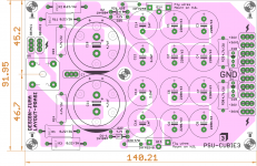
prasi: The CM layout you show in post #258 looks good. I would like to point out one thing to consider. It shows mounting a bridge rectifier like the Vishay GBPC-W. This will work fine if the user sets the current bias low. However, if a person wants to have an Iq of 1 A or more though it, this rectifier will get quite hot, in my experience. I do not like to mount things hot near any elko caps, which would shorten their life. With a higher Iq like this, the user might consider mounting the rectifier off board. Notice juma mounted his on the bottom plate in post #1. Or a person could use Schottkky diodes or some other diode with a low I F which would not get so hot.
Has anyone built this successfully, with one of my layouts? was the full sentence. I am aware of post #99, but as far as I know, that was not with my layout. Thanks everybody for being so helpful!!! I'll get this sucker working. I want to hear it. Cubie was fun, and Cubie2 is great!!!
Has anyone built the Cubie3 with Prasi's or Marsupialix PCB. ? Is it working ?
Just want to make sure the pcb is ok before starting to solder components.
Thanks
Eric
prasi: The CM layout you show in post #258 looks good. I would like to point out one thing to consider. It shows mounting a bridge rectifier like the Vishay GBPC-W. This will work fine if the user sets the current bias low. However, if a person wants to have an Iq of 1 A or more though it, this rectifier will get quite hot, in my experience. I do not like to mount things hot near any elko caps, which would shorten their life. With a higher Iq like this, the user might consider mounting the rectifier off board. Notice juma mounted his on the bottom plate in post #1. Or a person could use Schottkky diodes or some other diode with a low I F which would not get so hot.
Hi propitious,
One could mount the bridge rectifier anywhere one wishes and run wires, one could also populate the power resistors from bottom sides. it would work fine like Juma's original build in post #1. After all its diy. I could make a design with MUR1560 with dual rectifiers and all the conveniences thrown in, but might result in a larger PCB.
whatever works for the designer, should work for all.
Also, this is a Class AB, not Class A like Cubie2 biased at 1A.
You could of course run the Cubie3 at 1A but if someone has it biased at 200mA the bridge mounted on the pcb will be fine.
BR
Eric
You could of course run the Cubie3 at 1A but if someone has it biased at 200mA the bridge mounted on the pcb will be fine.
BR
Eric
Hi,
I read that CM can be problematic with class AB amp. I normally use them with class A.
Did anyone have issue with Cubie3 and it's CM ? My bias will be about 250mA.
Thanks
Eric
I read that CM can be problematic with class AB amp. I normally use them with class A.
Did anyone have issue with Cubie3 and it's CM ? My bias will be about 250mA.
Thanks
Eric
Hi,
I read that CM can be problematic with class AB amp. I normally use them with class A.
Did anyone have issue with Cubie3 and it's CM ? My bias will be about 250mA.
Thanks
Eric
CM with feedback can be problematic with class AB amp.
Juma CM + Cubie3, Juma will tell you in first post if it has problem 😀
Cubie 3 Turbo
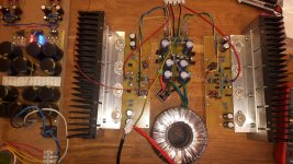
I'm testing a Cubie 3 with 46V rails.
So far it's sounds explendid 🙂
A bit high current (~8mA) on drivers, so the BC's runs att 45-50 celsius.
Drivers are 2SA1930 / 2SC5171.
Outputs are two pairs of 2SJ55 / 2SK175.
The preamps are Juma's. Complementary Jfet's cascoded with BC550/560.
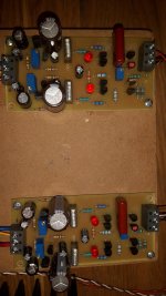
Every has it's own regulator onboard.
Very low noice and low distortion.
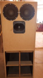
Speakers are BLH with Beyma 8G40's and CP380M on short horns.
/Figge
I'm testing a Cubie 3 with 46V rails.
So far it's sounds explendid 🙂
A bit high current (~8mA) on drivers, so the BC's runs att 45-50 celsius.
Drivers are 2SA1930 / 2SC5171.
Outputs are two pairs of 2SJ55 / 2SK175.
The preamps are Juma's. Complementary Jfet's cascoded with BC550/560.
Every has it's own regulator onboard.
Very low noice and low distortion.
Speakers are BLH with Beyma 8G40's and CP380M on short horns.
/Figge
Attachments
Hi Prasi,is it possible to post this for home etching?
Hi Thimios,
Completely forgot about your request... Here are the pdfs, whether they are still relevant?.
So sorry thimios.
regards
Prasi
Attachments
Last edited:
I'm testing a Cubie 3 with 46V rails.
So far it's sounds explendid 🙂
A bit high current (~8mA) on drivers, so the BC's runs att 45-50 celsius.
Drivers are 2SA1930 / 2SC5171.
Outputs are two pairs of 2SJ55 / 2SK175.
The preamps are Juma's. Complementary Jfet's cascoded with BC550/560.
Every has it's own regulator onboard.
Very low noice and low distortion.
Speakers are BLH with Beyma 8G40's and CP380M on short horns.
/Figge
Nice build Trollet,
except o/p, rails and drivers, did you change anything else from the schema?
Nice big PCB, reminds me of the JLH2003 PCB I did..
what is the bias you are running?
regards
Prasi
Well Prasi there's not much changes.
Jfets lies about 7 to 8 mA Idss.
The emitter resistors for drivers are 39R, maybe on the lower side. I did try KSA1220 and KSC2690 as drivers and it didn't work at all.
I don't really know why but guess it has something to do with saturation. Just swapped to the Toshibas instead and it worked fine.
Sometimes LTSPICE don't know what it's doing... Or is it me😀
I run at 300 mA bias now. The HS for regulators run at 40C but I plan to bolt them to a aluminium bottom plate so I guess they will manage a bit more. Output mosfets works at 28C so 5 or 600 mA may be plausible.
Only thing with PCB's is that a big toroid makes it tight to match width to 19 inch. Should have made them less slighter
Just waiting for some upc1237 now that I guess Trean from a Norway forgot when he dumped his "to do things" this night passing by 😕
/Figge
Try to install your transformer like stand up (on the side with an L shaped support) in case your heatsinks tall enough.
It's not tall enough @garborela. But with shoehorn and a bucket Vaseline I will manage to get it there 
/Figge
/Figge
Is this amp ok w 4 ohm load ?
I have an amp I’m not using, it has a sturdy power supply at +/- 36vdc from a 600va, 56Vct xtrm and the heatsinks are each 0.5 c/w (same as Hafler 220)
I know the supply is overbuilt for a class AB amp but it’s time to build the Cubie3
Will only 1 pair of output device (ECX10..) be ok for 4 ohm load with a +/- 36 v supply?
What power can I expect into 4 ohm ?
Thanks
Eric
Last edited:
- Home
- Amplifiers
- Pass Labs
- Cubie3