Hi Ammel68,
I have attached new gerbers, ones that have a drill file in txt format . see if this is what you require.
reg
Prasi
Hi Prasi,
Sorry for the delay...I just read your post.
Yes, your .TXT drill file works in Sprint. After I made some adjustments under the Drill data column, everything fell into place.
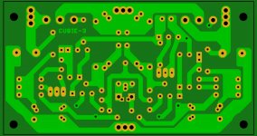
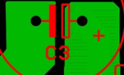
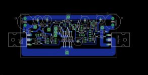
Looking at your bottom copper layer, parts of some of the wider traces look as though they're made up of a series of small traces stacked upon one another(or parallel to one another) as shown in the photo below.
Is that how you laid out some of the wider traces?
Thank you for the Gerbers and I learned something new.🙂
Attachments
Hi Prasi,
Sorry for the delay...I just read your post.
Yes, your .TXT drill file works in Sprint. After I made some adjustments under the Drill data column, everything fell into place.
Looking at your bottom copper layer, parts of some of the wider traces look as though they're made up of a series of small traces stacked upon one another(or parallel to one another) as shown in the photo below.
Is that how you laid out some of the wider traces?
Thank you for the Gerbers and I learned something new.🙂
Hi,
Actually thats how eagle CAD handles polygons and the visibility of lines is due to computer display (if you zoom in enough, the lines disappear). It doesnt create any problems when either doing diy etching or making professional PCBs (I have done both ways with earlier PCB's). If you are doing the PCB in sprint, make an appropriate polygon (or "zone" , I think its called) that encompasses the polygon copper area.
reg
Prasi
Last edited:
If you are doing the PCB in sprint, make an appropriate polygon (or "zone" , I think its called) that encompasses the polygon copper area.
Prasi, you are correct.🙂
I traced over one area(or polygon) of your board after clicking on the "zone" option.
The one I did is on the left and there aren't any more lines.
It's good to know that the lines won't have any effect on board manufacturing, though.
Attachments
 . Doing this for all "zones" will solve any potential problem with "eagle-sprint" imports (I feel).
reg
Prasi
Can anybody scrutinize the layouts I've posted for a mistake. I rebuilt the amp on the new board, and I get approx. 1/2 amp current draw, but something starts smoking almost immediately and I unplug. Got immediate smoke on old board as well. Something is wrong, but I haven't been able to locate it. Has anyone built this successfully, with one of my layouts? Pretty discouraged, I guess.
Attachments
Can anybody scrutinize the layouts I've posted for a mistake. I rebuilt the amp on the new board, and I get approx. 1/2 amp current draw, but something starts smoking almost immediately and I unplug. Got immediate smoke on old board as well. Something is wrong, but I haven't been able to locate it. Has anyone built this successfully, with one of my layouts? Pretty discouraged, I guess.
Hi,
Thats bad luck. Dont be discouraged. Can you post a photo of your laterals? did you buy those from reputable/ confirmed source? Also did you use all trannies as per the orginal schematic ? or did you make any substitutions? My layout exactly confirms the schematic as I used eagle CAD, there I am quite confidant. However, I will recheck again, just to confirm the devices.
reg
Prasi
Laterals are suspect. I will obtain devises from known trusted source. BC547 are BC550, BC557 are BC560. Everything else per original. I don't leave it plugged in long enough to tell exactly what is creating smoke, atho' I have been tempted. If I was able to say part x is burning, that might give someone an idea of what is wrong.
Edit: Just placed order for new laterals from tech-DIY. That's where I got them for Cubie and Cubie2, which worked great.
Edit: Just placed order for new laterals from tech-DIY. That's where I got them for Cubie and Cubie2, which worked great.
Last edited:
Laterals are suspect. I will obtain devises from known trusted source. BC547 are BC550, BC557 are BC560. Everything else per original. I don't leave it plugged in long enough to tell exactly what is creating smoke, atho' I have been tempted. If I was able to say part x is burning, that might give someone an idea of what is wrong.
Edit: Just placed order for new laterals from tech-DIY. That's where I got them for Cubie and Cubie2, which worked great.
Great. Best always with known source.
Still would like to take a look at the laterals. In another thread someone posted a lateral's photo with "TOSHIBA" printed. Can you believe that? Lats are made by Hitachi/Renesas. Fakers use whatever "stamp/print" is handy, it seems😀😀😀
Hi,
Thats bad luck. Dont be discouraged. Can you post a photo of your laterals? did you buy those from reputable/ confirmed source? Also did you use all trannies as per the orginal schematic ? or did you make any substitutions? My layout exactly confirms the schematic as I used eagle CAD, there I am quite confidant. However, I will recheck again, just to confirm the devices.
reg
Prasi
OK... re-Checked the devices used in eagle.
SK170/SJ74 are DGS (looking from flat side)
BC547/557 are CBE (looking from flat side)
BC639/40 are ECB (looking from flat side)
lats are GSD. (looking from print side)
(Left to right side ofcourse!)
So the layout and sch are consistent.so from my side everything looks ok.
reg
prasi
Hey, thanks so much for checking. I have checked and rechecked everything, and have done spot checks on random things from time to time. I can find nothing amiss. I checked all transistors (except latfets, since I don't need matched devices, and I don't know what they should read anyway). We'll see what happens with known good latfets. Thanks again!!!
See post # 99... Has anyone built this successfully....
Testing Lateral MOSFETs (please read the whole text):
Attachments
Last edited:
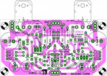
Are you aware that layout has 2 ground points (S-GND and P-GND) and that both should be connected to main ground ?... Something is wrong...
If not, the JFETs (and not only them) will burn.
Also, your k170 is the wrong way round (maybe some other components too, but it's hard to follow your layout (post #185) - too many collors and strange elements (X1). Good pictures of actual boards would be better.
Last edited:
Good catch!, which I missed somehow. K170 needs to be rotated by 180deg. others are OK.Also, your k170 is the wrong way round (maybe some other components too, .
That strange element is an ordinary 2 pin terminal block with 5mm pitch🙂 + it has some additional pads 2.54mm pitch so that people can use whatever is handy.strange elements (X1).
Thanks, juma!!! Grounds are (and were) connected together. Will rotate K170. I appreciate you taking a look!!!
Got home, flipped K170, still got smoke. Time to test the latfets.
It looks like the flipped K170 was introduced with the prasi revision. Not throwing stones, just sorting out the situation. On my original, the K170 is as it was on juma's layout. They both emit smoke at my house. On prasi based (larger) layouts, please flip the K170. Thanks.
It looks like the flipped K170 was introduced with the prasi revision. Not throwing stones, just sorting out the situation. On my original, the K170 is as it was on juma's layout. They both emit smoke at my house. On prasi based (larger) layouts, please flip the K170. Thanks.
Last edited:
Has anyone built this successfully, with one of my layouts? was the full sentence. I am aware of post #99, but as far as I know, that was not with my layout. Thanks everybody for being so helpful!!! I'll get this sucker working. I want to hear it. Cubie was fun, and Cubie2 is great!!!
Last edited:
Hi marsupialx,Has anyone built this successfully, with one of my layouts? was the full sentence. I am aware of post #99, but as far as I know, that was not with my layout. Thanks everybody for being so helpful!!! I'll get this sucker working. I want to hear it. Cubie was fun, and Cubie2 is great!!!
Any updates on your build?
Reg
Prasi
Has anyone built this successfully, with one of my layouts? was the full sentence. I am aware of post #99, but as far as I know, that was not with my layout. Thanks everybody for being so helpful!!! I'll get this sucker working. I want to hear it. Cubie was fun, and Cubie2 is great!!!
Hi
I am the guy from post #99 and here is my layout that worked immediately. It is surely not the most elegant one, I wanted to reuse the heatsinks and tappings from an ACA build, but it works and the amp sounds really good.
Attachments
- Home
- Amplifiers
- Pass Labs
- Cubie3