Please check out the Exicon or AlFet Dual Die Lateral Mosfets to get more power and avoid the use of source resistors. I think that would be the best solution to keep the existing PC design.Adding a second pair of output devices hugely improves the class A performance. I lowered the bias to 700mA (for a 32W idle dissipation) and got 60W into 8ohms and 30W into 4 (with class B headroom of 160W).
Shouldn't need the copper heat-spreaders in this config (lower output per device and output spread over heatsink with more devices).
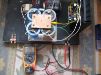
I try to set up the Cubie 3.
At the moment my rail voltage over 39 VDC, because of that is higher the lowest bias I'm able to set up 220-230mA.
My PS not regulated that would bring down the rail voltage. I have only this at the moment.
The PS transformer I have 27.5-0-27.5 ACV and 250 Va.
I have a large heatsink, just got slightly warm after 30 minutes.
I also have a 2x25 VAC transformer 250Va.
I may replace it the one is in the test model now so I can have lower bias in case it is too much at 39V rail voltage.
The offset voltage settled down after I grounded the signal input, Yellow alligator wire, before was jumping around between -3 to +3V.
The input terminal acted as an antenna very likely.
I wait one hour or so and after sound test it.
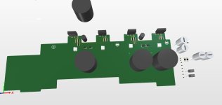
This is Prasi PCB design and of course thanks Juma.
At the moment my rail voltage over 39 VDC, because of that is higher the lowest bias I'm able to set up 220-230mA.
My PS not regulated that would bring down the rail voltage. I have only this at the moment.
The PS transformer I have 27.5-0-27.5 ACV and 250 Va.
I have a large heatsink, just got slightly warm after 30 minutes.
I also have a 2x25 VAC transformer 250Va.
I may replace it the one is in the test model now so I can have lower bias in case it is too much at 39V rail voltage.
The offset voltage settled down after I grounded the signal input, Yellow alligator wire, before was jumping around between -3 to +3V.
The input terminal acted as an antenna very likely.
I wait one hour or so and after sound test it.
This is Prasi PCB design and of course thanks Juma.
Attachments


Hi Gaborbela,
I’ve had a pair of Cubie3’s built and mounted to a heatsink for quite a long time, I experienced the same wild output offset when first powered up and rather than track down what was wrong I took the lazy path and moved on to the next project on the bench. I will have to revisit this one, following with rekindled interest.
I’ve had a pair of Cubie3’s built and mounted to a heatsink for quite a long time, I experienced the same wild output offset when first powered up and rather than track down what was wrong I took the lazy path and moved on to the next project on the bench. I will have to revisit this one, following with rekindled interest.
I think something is with the PCB design.
I connected the signal and now listening the first CD.
At second power up I had the same issue -16.3 VDC offset again even with the signal ground connected.
But was stable not jumping like before.
I sorted the signal Ground to the main Ground with an alligator clip and I could set up the bias and the offset also close to 0V, otherwise not!
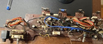
I will upload a picture soon. Yellow wire..
Is not a bad sounding amplifier at all, I write this way because I only listen my first CD and in one channel only.
It deserve to find the problem and fix it.
I encourage you to do the same as I did.
Soon I will measure on the PCB the speaker Gr and the signal Gr and the caps-bank Gr.
I want to measure 0 Ohm or close to 0 Ohm between them.
Greetings
I connected the signal and now listening the first CD.
At second power up I had the same issue -16.3 VDC offset again even with the signal ground connected.
But was stable not jumping like before.
I sorted the signal Ground to the main Ground with an alligator clip and I could set up the bias and the offset also close to 0V, otherwise not!
I will upload a picture soon. Yellow wire..
Is not a bad sounding amplifier at all, I write this way because I only listen my first CD and in one channel only.
It deserve to find the problem and fix it.
I encourage you to do the same as I did.
Soon I will measure on the PCB the speaker Gr and the signal Gr and the caps-bank Gr.
I want to measure 0 Ohm or close to 0 Ohm between them.
Greetings
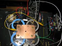
I checked the other PCB (not mounted to any heatsink yet).
There is no connection between the speakers Gr and the signal Gr.
Something fishy there. Maybe an extra 10R or less resistor between the two ground would be the solution?
One channel works well.
All that I found accidentally when my offset was jumping up and down.
There is no connection between the speakers Gr and the signal Gr.
Something fishy there. Maybe an extra 10R or less resistor between the two ground would be the solution?
One channel works well.
All that I found accidentally when my offset was jumping up and down.
Nice quality parts in your build Gabor😉
That makes sense now, Prasi usually makes a note on the pcb to connect signal gnd with wire to power ground.
Your observations are the same as mine, I forgot that I couldn’t set the bias current either.
Wow, this could be an easy fix!
Why didn’t you start your build 2 years ago .
.
That makes sense now, Prasi usually makes a note on the pcb to connect signal gnd with wire to power ground.
Your observations are the same as mine, I forgot that I couldn’t set the bias current either.
Wow, this could be an easy fix!
Why didn’t you start your build 2 years ago
.@gaborbela,
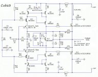
Please take a look at my post #212 and the next post, and look at the pic of the pcb I drew up. The intent is to bring the input signal + and Gnd from the RCA connector to the pcb and then run a wire from the SIG GND to the star ground on your power supply (which should be fairly short in length) as the NOTE says. The SIG GND does not connect to PWR GND on the pcb. The reason for that is from the second to the last sentence that juma wrote in his post #1. I am pretty sure prasi intended the same thing on his layout, although I did not check it out.
If you wonder if it is worth the effort to get the Cubie3 working, please read the note my wife wrote to me in post #213.
I see it even in the Schematic you posted at #212.
Unfortunately I saved a different Schematics and on that there is no any sign for the return signal Gr.
My fault, I always think if modified (later) it is better...... 😴😢
Thanks for your post. I will ad a 10R 1W resistor between the signal Gr and the speaker Gr.
It will be good enough for me. Of course I do not have the regulated PS neither that PCB.
I use those large caps that all, different.
Attachments
Very nice amp you built! Are you using Exicon or Hitachi/Renesans laterals?@gaborbela,
Please take a look at my post #212 and the next post, and look at the pic of the pcb I drew up.
At the time of my build I had some Hitachi. Now I use Exicon LatFets, which I think sound the same.
Also, the ps I drew up and juma drew up is a cap-multiplier, not a regulated supply. It is very quiet, and I measure less than 0.1 mV AC on its output. On your supply, the copper plate between your caps is your star ground to connect to. Since this is diy, if you have time you may want to try connecting the Sig (IN-) Gnd to your star ground with a wire as it looks like Prasi intended, and connect your speaker post ground (-) (on your chassis) to your star ground with a wire instead of connecting the speaker - post to the Gnd on the pcb. Finally, connect the GND pad on Prasi pcb to star Gnd with a wire also. You may think it sounds better and is more stable that way, and I think that is the way Prasi and juma instended. You can always switch it back if you want.
Also, the ps I drew up and juma drew up is a cap-multiplier, not a regulated supply. It is very quiet, and I measure less than 0.1 mV AC on its output. On your supply, the copper plate between your caps is your star ground to connect to. Since this is diy, if you have time you may want to try connecting the Sig (IN-) Gnd to your star ground with a wire as it looks like Prasi intended, and connect your speaker post ground (-) (on your chassis) to your star ground with a wire instead of connecting the speaker - post to the Gnd on the pcb. Finally, connect the GND pad on Prasi pcb to star Gnd with a wire also. You may think it sounds better and is more stable that way, and I think that is the way Prasi and juma instended. You can always switch it back if you want.
Sorry guys (Vunce & gaborbela), but I don't get it...
How and why does one decide to start a build and rejects to read even a such short instruction ?
I clearly wrote in post #1 : "Signal-ground and power-ground are led to star-ground by separate wires."
Can't be simpler than that and it's still ignored. 😏
How and why does one decide to start a build and rejects to read even a such short instruction ?
I clearly wrote in post #1 : "Signal-ground and power-ground are led to star-ground by separate wires."
Can't be simpler than that and it's still ignored. 😏
My PCB was stuffed about 2 years a go.
Now I have more time to test some of those stuffed PCB's.
Totally I forget. I did read before I started this project multiple times but that was 2 years a go.
I have no excuse for now, I supposed to re-reed it again before I powered her up.
It is good to happened with me, this way Vunce get help also. 😀🤣
Thanks Juma for the notice and for the amplifier!
Hello Juma,
Can one place a short across R9 if he wants to put the amp in standby mode?
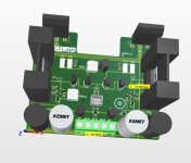
I am rebuilding a Toshiba SC-330. It will have a main board and the amps will be on different pcbs, this way I can easily replace the amp modules. It will have active cooling and will be a nice test bed for future class ab amps. I plan to use the Cubie3 as the first modules.
Because I have some small signal laterals I decided to use them in the vas and upped the current to 20ma. Ltspice predicts much lower thd.
On the mainboard initially I planned to put an Amp Camp but changed my mind and now I will have the amp modules on different pcbs.
Can one place a short across R9 if he wants to put the amp in standby mode?
I am rebuilding a Toshiba SC-330. It will have a main board and the amps will be on different pcbs, this way I can easily replace the amp modules. It will have active cooling and will be a nice test bed for future class ab amps. I plan to use the Cubie3 as the first modules.
Because I have some small signal laterals I decided to use them in the vas and upped the current to 20ma. Ltspice predicts much lower thd.
On the mainboard initially I planned to put an Amp Camp but changed my mind and now I will have the amp modules on different pcbs.
Attachments
Hi schultzsch,
shorting R9 will cut off the bias and put the amp in stand-by mode.
Before doing so I would test what happens to DC offset at output in that case.
Returning from standby mode also needs checking because there are few caps in circuit that'll be recharging.
All tests easily done with fuse in trafo's primary and load resistor instead of speaker at the amp's output.
Thanks juma.
If that is not going to work I can try same principle with the bias pot. Use a big resistor like 10k to keep the ops at a low bias current when in standby and a smaller resistor in parallel with it to bias the amp higher thus turning it on.
I have a front switch on the amp that was switching the speakers and now want to use it for turn on/stanby. Being a 3 position I can use it for standby/low bias(summer)/high bias(winter)
How low can I set the current in the ops for the standby mode?
Few mA I guess, maybe 10 - I never tested that.
I'd consider mute function rather than standby, but it's your needs and decisions.
Low/high bias makes sense in certain conditions too.
I'd consider mute function rather than standby, but it's your needs and decisions.
Low/high bias makes sense in certain conditions too.
- Home
- Amplifiers
- Pass Labs
- Cubie3