Nothing read dead short on a transistor. The Darlington reads as a diode from B to C (same as an ordinary transistor) and as two series diodes from B to E but there is often a resistor inbuilt across B and E of the second internal transistor (the one of the pair you can not get directly to the base) and so that means B to E reads a bit less than two diodes and a bit more than one.
C to E should always read open circuit when the leads are the correct polarity.
C to E should always read open circuit when the leads are the correct polarity.
Just the ways it's drawn then, but i understand now.
The only differences are less power dissipation and maximum peak collector current.
'C to E should always read open circuit when the leads are the correct polarity.' -same as any BJT then
I ended up getting the ones you suggested they should do the job
i also had to order the caps, real odd sizes in those creeks because of the very shallow depth of the casing, they are only 23mm high
I ended up getting the ones you suggested they should do the job
OK, although like I said I didn't study them in detail... other Darlington's are available 😉
It might be worth you running the fault channel up with the outputs removed and with the base and emitter pads of either the NPN or PNP Darlington linked out. Obviously no load attached. Nothing bad should happen and I think it should all bias up and work with a reasonably correct midpoint.


You can test it with the scope 🙂 Its worth trying. Also make sure the diodes between the two bases are OK and not open circuit or intermitent. Maybe just replace them. They are not critical.
Yep one of the first things I checked forgot to mention that zener was knackered as well for some reason
Lol, what Zener would that be?
Those are just two ordinary diodes (1 amp). Its worth checking and maybe just replacing those and the two little drivers simply because anything could have happened with dodgy outputs. They could have taken a hit.
Feeding time... I'll look in later 🙂
Those are just two ordinary diodes (1 amp). Its worth checking and maybe just replacing those and the two little drivers simply because anything could have happened with dodgy outputs. They could have taken a hit.
Feeding time... I'll look in later 🙂
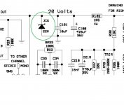
That one is just a shunt regulator for the preamp section. Any issues there should not effect the power amp at all because the audio stages are AC coupled. If its faulty (short) then the 1k5 feeding it might be stressed as it would see over 2 watts dissipation.
yep famous last words.Im going to keep it shut next time!Famous last words are those, 'there's not a lot wrong with it'. Normal fault-finding rules apply.
🙂
so the fault that was on the other channel,is now on this one 🙂
ive been trying to look at it logicaly so i have replicated everything i did with the other side
and i have exactly the same cenario as there was with the other one
im using a light quick blow 1A fuse while testing and i have the same as i did before, once you power it up, then turn it off, put the fuse back in with it off i get a flash and the fuse blows, like there was a dead short, but for the life of me i cant find one, but it must be there.
You need to approach it differently. Use the bulb tester and fit the fuse to one channel only and then fault find on that channel without removing the fuse. If you look at the circuit you will see there are only a couple of direct possible paths for current to flow.
So power it up and first measure the supply voltage. If its zero then you have a dead short somewhere. If its a few volts then you have a conductive path somewhere but not a short.
Favourite would be an issue with the mounting of the upper NPN output and a possible short to the heatsink. There are also two caps decoupling the rail. And that's it. There is nothing else that could conduct current. Obviously if both output transistors were short or were fitted in the wrong place (NPN for PNP etc) then that would do it.
So be logical. If you still can't find anything wrong then remove both transistors and see if the rail come up. Keep the fuse in at all times.
so i havent got the heatsink on at the moment, so it isnt shorting to that
what i cant understand is the channel that 'was' faulty, isnt now and that was ok when i put the transistors from the other channel into that one
The faulty channel now has brand new ones, so i know they are ok, as are all the others
so only one channel lights the lamp, and im concentrating on that one
ill do as you suggested and report back later 👍
well with the good channel disconnected it just blows the fuse, so ill have to have a look without the lamp
something is a miss here.
i have 156vac(not mv) between the casing ground and the transformer ground
something is a miss here.
i have 156vac(not mv) between the casing ground and the transformer ground
Last edited:
what i cant understand is the channel that 'was' faulty, isnt now and that was ok when i put the transistors from the other channel into that one
Don't go down the rabbit hole 🙂 Fault find on how it presents now at this moment in time.
The faulty channel now has brand new ones, so i know they are ok, as are all the others
Lets hope so but never discount them as being not to blame.
well with the good channel disconnected it just blows the fuse, so ill have to have a look without the lamp
Careful voltage checks even if the bulb is lit are still very valid. Even if the supply is only at 4 or 5 volts it still works as a fault finding approach.
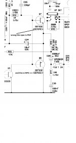
it has to be this version as each base has a diode.I think you have this version. Two diodes as a bias generator but these should be safe to link out.
View attachment 1031748
both diodes are fine
so i am getting realy confused now
i put the original outputs back in the 'so called 'faulty channel and the lamp is off
the 2 new transistors i took out of that channel are both blown
now these transistors were brought from RS and i tested them as you described before hand and they were both good.
i think i have been thrown a bum steer here
if you look at the section attatched(wrong) you will see the references are wrong for each transistor and this is what i was working to
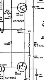
now look at the one you provided, that im sure now is my version and you will see, although it isnt very clear, the transistors are reversed in the configuration and have the correct references on them
if you look at the section attatched(wrong) you will see the references are wrong for each transistor and this is what i was working to
now look at the one you provided, that im sure now is my version and you will see, although it isnt very clear, the transistors are reversed in the configuration and have the correct references on them
Attachments
so i recon this is fixed
the components are reversed in the amp compared to the drawing
both channels are on now, no lamp
0.0v dc both speaker terminals
but i have 2v ac-is this ok?
the components are reversed in the amp compared to the drawing
both channels are on now, no lamp
0.0v dc both speaker terminals
but i have 2v ac-is this ok?
Well spotted 🙂 Service manuals often do have errors (unfortunately).
You shouldn't have any AC across the speaker terminals. That is worth looking at with the scope to see exactly what is present and why the meter is registering something. All you should see is a straight line on the scope. Use DC coupling (because the output is already AC coupled) and set the scope to 1 volt/div.
You shouldn't have any AC across the speaker terminals. That is worth looking at with the scope to see exactly what is present and why the meter is registering something. All you should see is a straight line on the scope. Use DC coupling (because the output is already AC coupled) and set the scope to 1 volt/div.
used the scope and there was no ac voltage in the end, but at least its clear, nothing on the meter either
weird things going on here though
only one channel working
3 din sockets at the back
plug it into one and you get sound direct from the cd player with the power off on the amp
plug it into another and it works as it should but only one channel
plug it into the other and the volume dont work but the sound goes up and down on one channel only using the balance control
so not sure what is going on here
Last edited:
- Home
- Amplifiers
- Solid State
- Creek 4040