Measure the one on the good channel for comparison. A four band resistor would be Orange/Orange/Silver and Gold.
What you describe of it burning up would be a classic symptom of high frequency oscillation and I think you mentioned earlier reading some AC value across the terminals but no DC.
Check the 10 ohm and 0.1uF in the Zobel network are OK.
What you describe of it burning up would be a classic symptom of high frequency oscillation and I think you mentioned earlier reading some AC value across the terminals but no DC.
Check the 10 ohm and 0.1uF in the Zobel network are OK.
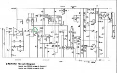
Harking back a little to what I understand of comments in the thread so far, the schematic at #77 isn't the same Version1 that poundy shows in #5. That's right, Creek had series variations, different versions and who knows how many undocumented levels of variation just within serial numbers 1,000-12,000, for example) It seems that this problem was caused by needing help from other manufacturers, hence variable parts sourcing and even design changes, in order to meet the unexpected demand.
In any case, I think the schematic should have Darlington output transistors BDT63C/64C or similar, as in series one (i.e. S1- V1)
In any case, I think the schematic should have Darlington output transistors BDT63C/64C or similar, as in series one (i.e. S1- V1)
I'm the one who put a diagram to have one under the eyes.
I had never paid attention to how much Creek modified its circuits in the same series 🙄
I had never paid attention to how much Creek modified its circuits in the same series 🙄
I just surfed a little on the different diagrams of the 4040 and it seems that there are more than 3 versions, not easy to help without being sure that it is the right one.
In the version identified by Poundy, I cannot find the 4 1N400X
In the version identified by Poundy, I cannot find the 4 1N400X
I think I've got it. It might be your DIN lead at fault (reversed). That connection to the balance control is an output, not an input. The input from the socket does go to the input selector switch.
Another possibility is that the lead may be OK but you have something that connects to those output pins and that is low impedance (or short) and so as you alter the balance it seems to do weird things.
Another possibility is that the lead may be OK but you have something that connects to those output pins and that is low impedance (or short) and so as you alter the balance it seems to do weird things.
so as a test i took those 2 leads off and if you use the aux plug everything works perfectly, on both channels,lovely and clear, but only with that plug
the other 2 sockets
tuner-only sound from one side, but not distorted
tape-realy distorted one channel works only
the other 2 sockets
tuner-only sound from one side, but not distorted
tape-realy distorted one channel works only
You will have to trace the signal careful with the scope I think.
Look at the circuit...
Lets pick pin 3 of the DIN sockets and look at both AUX and Tuner. The input selector selects one or the other and so if AUX is working OK then so should the other Tuner input.
The Tape Monitor input seems to have its own one transistor amp and so its worth checking the DC conditions on these.
Those points are the switch. The moving wiper contact is the line with the arrow and it can connect to any of those three points. The line with the arrow is the input to the preamp stage. So as drawn the Phono input is selected.
on the tuner din it says 5R and 1L are not used yet they are both connected directly to ground.that cant be right
I can't just get the hang of that. 5 and 3 are shown as the pins for the inputs.
You might be best just working it out from what you see and checking continuity. The tuner input socket should only have two connections plus ground and they should be 5, 3 and 2 for the ground (according to the Creek circuit). 2 is the middle one... I know, weird but 2 is the middle one.
You might be best just working it out from what you see and checking continuity. The tuner input socket should only have two connections plus ground and they should be 5, 3 and 2 for the ground (according to the Creek circuit). 2 is the middle one... I know, weird but 2 is the middle one.
i think im going to have to do just that, i cant realy trust any of this thats laid out
you see if 1 and 4 are connected to ground then that will directly have an effect on the conversion back to the phono conversion plugs wont it
you see if 1 and 4 are connected to ground then that will directly have an effect on the conversion back to the phono conversion plugs wont it
Be logical. I would set about it by applying a signal to one channel only and following it from the socket to the switch and then to the preamp. Also make sure there is no excessive crosstalk from the channel being tested into the other channel.
I notice Mooly last shows and I imagine refers to Version 1, Series 3 schematic whilst the OP sets out with Series 1, Version 1, Rev.3 - a different and computer generated draft for clarity, I assume. Confusion between the comments and perhaps pin assignments on the DIN sockets may have an explanation (like DIN standards were often ignored by manufacturers ) but it would help to know that we're on the right page by checking any extra classification details shown at the top and bottom margins of these re-drafted schematics.
When you compare the details, you find that whoever did the re-drafting wasn't being consistent with the earlier Version/ Series numbers and apparently added a revision (Rev) reference too. Consequently, there are more than a few odd differences which pop up when you refer to the wrong schema. and say, an opamp appears where it shouldn't be in Version 1, Series 1.
When you compare the details, you find that whoever did the re-drafting wasn't being consistent with the earlier Version/ Series numbers and apparently added a revision (Rev) reference too. Consequently, there are more than a few odd differences which pop up when you refer to the wrong schema. and say, an opamp appears where it shouldn't be in Version 1, Series 1.
Last edited:
given up on this one for now as it is taking up too much of my time
i know one thing i wont be getting one of these again!
i know one thing i wont be getting one of these again!
- Home
- Amplifiers
- Solid State
- Creek 4040