Sounds interesting 🙂
I always say this but have to be logical and work with whatever fault is presenting and this is where the scope excels in faults like this.
I would pick one input, lets say tuner and then trace the signal through on both channels. Measure one channel, then the other. You should see the audio signal at the emitter of Q1 and Q2 as first quick easy checks.
Favourite problems (at a guess without seeing it) would be switch problems and perhaps cracked print around the volume and balance controls.
now ive got 22v dc on both sets of speaker terminals,so god knows how that has occured. so im packing it in for tonight
The amp is AC coupled and so I'm guessing you are measuring this with no load attached and so just reading a bit of leakage (which is normal) through the large coupling caps. As soon as a load is connected it will pull the voltage to zero. If the midpoint is correct at around half supply voltage then its OK.
fair enough, i trust what you are saying as you would know, but i just ask myself that question,when i turned it on for the first time i had 0v on both immediatly, so i always ask what has changed
I can't answer that one without trying it but I do know the theory is sound 🙂 It is common to read DC voltage at the floating end of a capacitor coupled amp.
In your case the amp may have been on a while and the cap will in fact charge very slowly via that 15k (is it 15k? its a bit blurry) feedback to the tone control. So the voltage on the terminals will fall over time. With a load its very quick, and you hear it as a thump in the speaker at switch on.
Try this. Here we have a cap supplied by 35 volts DC and feeding a 15k resistor. The sim shows the charging over 2 minutes. Try it when you change the resistor to 8 ohm like a speaker.
Attachments
Ah right so there is something in what you are saying here. Ii observed the voltage on the scope and gradually, but consistently drops as you watch it. I didn't watch it go to 0v,,but I just don't understand how it can be 0v on switch on one min and later 22v,gradualy discharging
I can't say, there are to many unknowns unless I saw it for myself. For example was it 22 or 2.2 or is the meter auto ranging and so having trouble locking to a moving target. Did you 'accidently' even for an instant short the speaker output. That would cause no damage but would instantly pullthe voltage down to ground.
So to many 'what ifs'.
🙂
So to many 'what ifs'.
🙂
have you tried to turn it on gradually (with a variable transformer) with a small resistor of 4ohm 0.5w connected at the output?
so i did try a load this morning
one channel seemed ok, this was with an input running from the cd player
the other one burned up the 4ohm load resistor and the 3.3ohm on he board, well i turned it off before it went completely
so ill check it out later
on the channel that didnt blow, the DC did dissapear as you said it would, i didnt realy have a chance to check the other, although i suspect it did as well
ok, you now have at least one channel that works (well, that doesn't burn) 😛
in which part of the world do you live?
in which part of the world do you live?
South mateok, you now have at least one channel that works (well, that doesn't burn) 😛
in which part of the world do you live?
Which is the 3.3 ohm?the other one burned up the 4ohm load resistor and the 3.3ohm on he board, well i turned it off before it went completely
Two things to look at. We know that an AC coupled amp can not pass DC into the load if we are sure the coupling cap is OK. So we can rule out any DC fault. That leaves AC and if that is the case then it almost always means instability and oscillation which is again a case of using the scope to see what is actually across the load.
i will look at this later as i have 3 to look at today, not including the creek, but i will get round to it.
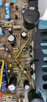
The 3.3 is as shown here
this is why i have had so much trouble with this amp, its not one drawing or the other, or even any of them sometimes
coupling caps are new
The 3.3 is as shown here
this is why i have had so much trouble with this amp, its not one drawing or the other, or even any of them sometimes
coupling caps are new
Attachments

Last edited:
Think 🙂i will look at this later as i have 3 to look at today, not including the creek, but i will get round to it.
The 3.3 is as shown here
this is why i have had so much trouble with this amp, its not one drawing or the other, or even any of them sometimes
coupling caps are new
That resistor is in series with the output. A 3.3 ohm and a 4 ohm speaker would pretty much halve the output voltage. I think you'll find its 0.33 ohm. If you fitted a small 3.3 ohm it would quite possibly burn up if you turn it up loud.
- Home
- Amplifiers
- Solid State
- Creek 4040