+1 😁LOL. It will irritate and annoy you, you will keep thinking and wondering...
so it will be back on the bench before to long 😉
so ive been having another go with this today and the below is where we are with it
ive had real trouble with this as it isnt realy one or the other of the schemes
so i have determined the fault is with one channel only, the left as i took the fuse out for the left and used the right perfectly normaly
so thus far:
volume control changed with new one-so its not that
balance control changed for a new one-so its not that
all 4 output transistors are new, and have been double checked
all other transistors have been out and back-all tested ok
all diodes tested and are ok
the zener is new
all track has been checked,double checked and triple checked, i can find no issue
the amp has been completly recapped(electrolitics only)
all resistors have been pulled and checked-all ok
all switches check out perfectly with continuity between common/no/nc contacts
phew
so not realy sure where to go from here other than checking all the other caps, but most of them i checked and all were ok where they were grounded
ive had real trouble with this as it isnt realy one or the other of the schemes
so i have determined the fault is with one channel only, the left as i took the fuse out for the left and used the right perfectly normaly
so thus far:
volume control changed with new one-so its not that
balance control changed for a new one-so its not that
all 4 output transistors are new, and have been double checked
all other transistors have been out and back-all tested ok
all diodes tested and are ok
the zener is new
all track has been checked,double checked and triple checked, i can find no issue
the amp has been completly recapped(electrolitics only)
all resistors have been pulled and checked-all ok
all switches check out perfectly with continuity between common/no/nc contacts
phew
so not realy sure where to go from here
other than checking all the other caps, but most of them i checked and all were ok where they were groundedSo here is what I would do... this is a bit of real dynamic fault finding as we need to work through every input and see what is happening 🙂 The amp must be on but we will not have any speakers connected at this stage. Volume on minimum and balance centred.
1/ Set your signal generator to around 200 millivolts peak to peak output (1kHz, no higher) and apply it to the Tuner input on pin 3 (look at the circuit).
2/ Make sure Tuner is selected on the front panel.
3/ Check for signal on what looks like C14. This is the cap that goes to the volume control. It looks like you will see a little less signal here than you apply at the input.
4/ Transfer the scope to the same point on the other channel. There should be no signal present.
5/ Now feed the input into the other channel (pin 5) and repeat the checks. Now this channel should have the same level of signal on its coupling cap feeding the volume control and the other channel should have zero signal.
That shows us the signal for that input is reaching the volume control and there is no weirdness between channels.
6/ Now connect the scope to the speaker output (make sure you have the correct channel) and turn the volume control up to get 4 volts peak (8 volts peak to peak).
7/ The other channel should have no signal at the speaker socket.
8/ As before, swap the input signal to the other channel and scope that channel. You should see the same 4 volts peak signal (proving channel balance and gain is correct). The other channel should see no signal.
9/ Apply the input signal to both channels. You should see 4 volts peak output from both speaker outputs. The balance control should swing the output higher on one side and lower on the other and vice versa as you rotate it.
Just seen your new post... I'll look later 🙂
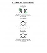
I'm going to say just use the scope to see where the signal ends up with your lead. DIN leads are a nightmare so as there is doubt you have to trace the signal... which is quicker than typing this 😉so the DIN lead i have is described as below
so is this compatible with the amp (what is the 3+5) ??
- 5-pin DIN plug (wired 3+5) to 2 x RCA phono sockets
Concentrate on the tuner input socket because only two of the pins are active and so it should be easy to which these are. I assume the other two are not connected to anything on the board (which is what it shows).
Those same pins will be the same on the other two sockets i.e. they are the input inputs. The other two pins are tape outputs, one controlled by the volume and balance control and one not.
Just work through it logically as I described to prove/disprove the amp really is OK.
Those 2 tuner pins that are unused go to groundI'm going to say just use the scope to see where the signal ends up with your lead. DIN leads are a nightmare so as there is doubt you have to trace the signal... which is quicker than typing this 😉
Concentrate on the tuner input socket because only two of the pins are active and so it should be easy to which these are. I assume the other two are not connected to anything on the board (which is what it shows).
Those same pins will be the same on the other two sockets i.e. they are the input inputs. The other two pins are tape outputs, one controlled by the volume and balance control and one not.
Just work through it logically as I described to prove/disprove the amp really is OK.
OK. It will be interesting because it is real fault finding and signal tracing to prove/disprove whether there is a real problem or not.
i am a bit unsure of how to ensure i have 200 mV from the generator, i guess this is via the amplitude?So here is what I would do... this is a bit of real dynamic fault finding as we need to work through every input and see what is happening 🙂 The amp must be on but we will not have any speakers connected at this stage. Volume on minimum and balance centred.
1/ Set your signal generator to around 200 millivolts peak to peak output (1kHz, no higher) and apply it to the Tuner input on pin 3 (look at the circuit).
2/ Make sure Tuner is selected on the front panel.
3/ Check for signal on what looks like C14. This is the cap that goes to the volume control. It looks like you will see a little less signal here than you apply at the input.
4/ Transfer the scope to the same point on the other channel. There should be no signal present.
5/ Now feed the input into the other channel (pin 5) and repeat the checks. Now this channel should have the same level of signal on its coupling cap feeding the volume control and the other channel should have zero signal.
That shows us the signal for that input is reaching the volume control and there is no weirdness between channels.
6/ Now connect the scope to the speaker output (make sure you have the correct channel) and turn the volume control up to get 4 volts peak (8 volts peak to peak).
7/ The other channel should have no signal at the speaker socket.
8/ As before, swap the input signal to the other channel and scope that channel. You should see the same 4 volts peak signal (proving channel balance and gain is correct). The other channel should see no signal.
9/ Apply the input signal to both channels. You should see 4 volts peak output from both speaker outputs. The balance control should swing the output higher on one side and lower on the other and vice versa as you rotate it.
Just seen your new post... I'll look later 🙂
Yes. Use the scope remembering to account for whether you use a X1 or X10 probe. If your meter can resolve low AC voltage then 200mv peak to peak would read as 70 millivolts.
It is not critical at all as long as you have enough to be useful and not to much that it overdrives everything.
It is not critical at all as long as you have enough to be useful and not to much that it overdrives everything.
You'll be back to it 🙂 Uisng the scope to trace the signals should be really interesting, its real fault finding to prove/disprove there is an issue.
so we are on this again.
so where we are.Im going to order a new lead as im not convinced by the one i have but....
i took the aux one off the board and with that removed and using the tuner one, it works ok on both channels, but only one one channel with the tape input
so still a way to go, but i cant move forward with confidence untill i know i have a good lead
That does sound a bit weird. I've never liked DIN connectors and there are just so many variations available but that is just odd that you have there. I assume it measures that when not connected to the amp at the other end.
what it is doing is tying one channel from the input to the output of the other, no wonder it doesnt work
ive ordered a new lead so we will see how it goes when i get that tomorrow
so much rubbish around thats the trouble
ive ordered a new lead so we will see how it goes when i get that tomorrow
so much rubbish around thats the trouble
Quite possibly yes (rubbish around) but there are lots of variations on DIN leads such as mirror image and reversed connections. Sometimes you can prize the plastic off and have a look and a rewire 😀
yeah not on these ones these days
they are mostly moulded
they used to have a split metal outer, but now they are all one piece and moulded
you can by realy good ones but i cant justify(well i couldnt before lol) spending £30-40 on a din/rca lead
maybe now looking back it might have been worth it,well we will find out tomorrow 🙂 (touch wood)
- Home
- Amplifiers
- Solid State
- Creek 4040