Well here we go, this should be interesting.
Left channel main fuse blown, so possibly a transistor fault.
As far as i can make out there are 3 versions of this, with 3 different schematics
first thing, serial number on the back of mine doesnt match with anything but i have a 63v supply so im going to assume at the moment i have a V1 model
The others appear to have a modified supply at 30v
vesions 2 and 3 have opamps, a bit more like the later version 5050
biggest problem now is the board is unmarked at all, so its all going to be tracing from here on with cross referencing the drawing.
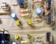
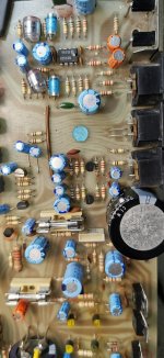
Attachments

You should be able to navigate your way around the output stages at least, without needing part numbers and lists. Most resistors have fairly common values for their particular roles and the larger types can be spotted from a metre away. Start with the big and work back to the smaller parts by a process of elimination, aided by a few voltage checks to ensure you're on the right track or at least narrowed the chances of error.
Repair techs coped with this situation every day in the valves/tubes and early solid state era. That's how it was - cheapest possible or no assembly set-ups, jigs and tooling at all - minimal documentation and often only sketched circuit diagrams to make sense of the mess you find inside the box. Fully engineered products must have been significantly more expensive to produce than it was to just hand-assemble them according to demand, as Creek and many other UK manufacturers would have done, back in the day.
I was going to suggest you label a sprinkling of resistors and transistors on the PCB in pencil, as a guide once you've identified a few but the graphite can be conductive so use a hard pencil grade sparingly. Marker pens are OK if you don't disturb the marks but today's inks are so-o-o safe that they simply wipe off with a touch - many are quite useless.
actualy ive been doing just that ian, the board actualy is almost transparent so its easy to follow your fingers from the front
It makes you realise how spolied you get sometimes with the detail on other brands
im still learning my way round the differential models, but im getting there slowly 👍
found quite alot wrong so far
It makes you realise how spolied you get sometimes with the detail on other brands
im still learning my way round the differential models, but im getting there slowly 👍
found quite alot wrong so far
What sorts of problems have you found so far? I haven't seen a 4040 in many years, let alone repair one.
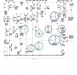
so i have identified its def a V1 amp and so far ive found as attached
i have to pack it in for today, but ive now got 15v on the speaker terminal, but i have the transistors removed so untill i get the new ones(ordered) i cant realy tell if what ive replaced will be it, and ive run out of time today to carry on testing.
circled in blue are the faults, green checked so far
Attachments
Anyway I've replaced those 2 darlington's
ive already replaced that burned out metal oxide resistor(R43) and tested the other transistors, they are all good.
I've got Blackpool illuminations on the faulty channel now so I'll check the rest over the weekend as i ran out of time tonight. Time for ☕ then a bit of TV then 😴
ive already replaced that burned out metal oxide resistor(R43) and tested the other transistors, they are all good.
I've got Blackpool illuminations on the faulty channel now so I'll check the rest over the weekend as i ran out of time tonight. Time for ☕ then a bit of TV then 😴
No sorry, its on now after I put all the new parts in, didn't have time to go any further last night. Can't be alot wrong,, there's not much in thereYou mean it burned up with a bulb tester in place? What burned?
Famous last words are those, 'there's not a lot wrong with it'. Normal fault-finding rules apply.
🙂
🙂
Of course, everything I do now is because of how you have guided me👍Famous last words are those, 'there's not a lot wrong with it'. Normal fault-finding rules apply.
🙂
ive been having another look at this and there realy cant be alot that could cuase the transistors to fail is there given all the other components around it are ok
im going to hazard a guess here before i test it tomorrow at either C29,30 or R44
All the other transistors are fine.
ive been trying to look at it logicaly R43 was open and ive replaced that.
Before i took anything out the lamp was off
im going to hazard a guess here before i test it tomorrow at either C29,30 or R44
All the other transistors are fine.
ive been trying to look at it logicaly R43 was open and ive replaced that.
Before i took anything out the lamp was off
R43 is the 0.33 in series with the speaker. The only thing that could see that off in a working amp would be overdriving the amp (playing it to loud) or if failure of a transistor did cause full rail voltage to appear on the resistor and that voltage caused the under rated 35 volt speaker coupling cap to pass lots of current into a speaker. That's a very plausible scenario actually.
well we will find out tomorrow, but for now im off out to play for a while,i need a drink after this week!R43 is the 0.33 in series with the speaker. The only thing that could see that off in a working amp would be overdriving the amp (playing it to loud) or if failure of a transistor did cause full rail voltage to appear on the resistor and that voltage caused the under rated 35 volt speaker coupling cap to pass lots of current into a speaker. That's a very plausible scenario actually.

So it was none of those components Inc that 3300 cap, so not a great deal left to check, unless one of the new transistors is faultyOK, enjoy 🙂
The cap could have 'failed' non destructively. When overvolted it passes lots of current, enough to zap the resistor but the cap survives. If you look at the circuit you will see the cap only feeds a 47k (so that will never pass any current) and the speaker which of course is a low impedance. So I think that is the most likely scenario, the cap has passed current, enough to zap the resistor, but the cap itself is still OK.
- Home
- Amplifiers
- Solid State
- Creek 4040