Ok , Bill ,
this is what I have done . I have 1 thermistor between everything and the chassis ground.
I will order the correct CL 60 in the morning .
From your sketch the thermistor is on the DC ground - correct ? and there is 1 on each
channel ?
Should I remove the thermistor I have already ?
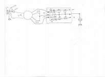
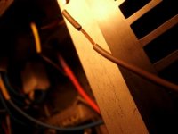
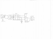
I have my windings as per this drawing ? I should wire them as you have drawn. One end of my secondary to the + and the other end to the - ..... I have wired 1 SEC to the + and the other SEC to the - ...
I hope your eyes are rolling back in your head and theres a smile on your face LOL
thanks for your patience and kindness
Rich
PS, the bottom transfo should be drawn into the circuit - It is 3am here 🙂
this is what I have done . I have 1 thermistor between everything and the chassis ground.
I will order the correct CL 60 in the morning .
From your sketch the thermistor is on the DC ground - correct ? and there is 1 on each
channel ?
Should I remove the thermistor I have already ?
I have my windings as per this drawing ? I should wire them as you have drawn. One end of my secondary to the + and the other end to the - ..... I have wired 1 SEC to the + and the other SEC to the - ...
I hope your eyes are rolling back in your head and theres a smile on your face LOL
thanks for your patience and kindness
Rich
PS, the bottom transfo should be drawn into the circuit - It is 3am here 🙂
Attachments
Last edited:
Hi Rich,
I am so glad you are still able to type up your posts.
Keep going like this and you will kill yourself!!!!!
Get that bulb wired up and use it every time you connect a new or modified project to the mains.
There are many in this Forum who say we should not and need not soft start a 300VA transformer. They are all wrong.
Your 300VA has a maximum continuous rating of 300VA, a 1.2A mains fuse allows a continuous throughput of ~290W. Fit a T1.2A to each 300VA transformer.
Will that fuse allow short term peaks in your music, YES! A 1.2A fuse will pass 2.5A for many seconds and pass 10A for a few hundred ms.
Will that fuse survive start-up, probably not. You have choices, fit a bigger fuse and reduce the protection afforded by the fuse rating or fit a soft start.
A CL60 may be sufficient to start up both 300VA transformers. I would try a pair of CL60 in series for the soft start. I find that series combinations or 20r 5W or 10r 5W resistors to be much cheaper and almost as good. I would use 60r or 80r to start up each 300VA and bypassed in ~200ms.
While you are still testing the light bulb becomes your soft start, so you don't need the CL60s nor the timer nor bypass relay to get started. A 2pole one way relay allows both transformers to be soft started separately.
Start by inserting each transformer wire into a separate receptacle of an insulated terminal strip.
Then begin by powering ONLY one transformer through the bulb. A 40W bulb is preferred at this stage.
Then test by powering both transformers through the bulb. If the bulb lights you have wired the primaries up wrong. Get through this first with nothing attached to that terminal strip except the transformer and the bulb fed supply.
Then add a rectifier to one transformer. Test.
add the second rectifier. test.
add one capacitor bank. test.
add second capacitor bank test.
add one amplifier. test. You may need to change to a 60W or even a 75W bulb at this stage.
add second amplifier. test.
get the message!!!!
Last edited:
Thanks Andrew
I followed Bills drawing - everything measures good up to the AC side of the PSU @ 23 v AC with a .1 difference between transfo output .
The DC side measures 62 with a .2 difference between channels ... this measurement is taken across + and -
The led lights up ,but have disconnected the amp boards till I check the DC value .
Any ideas .... I did find a short in the pcb at the weekend ,but have managed to get it sorted out ... I WILL NOT BUY CHINESE BOARDS AGAIN 🙂
Rich
Wheres the heat ?
I have a problem with the fets .... no heat . The front 3 on both channels
offer a DC reading ,but the rear 3 of each channel do not ... If I have made a mistake ,I have done it on both amp boards .
I have spent a bit of time trying to trace it ,but there is so much I dont understand about the component functions that I dont know where to start .
Can someone help me please .... It would be great if that person had skype too !
thank you , Rich ..... so bloody close 😡
Sorry, I just got my internet service back an hour ago. We were down since last night.
The chassis should be directly connected to the IEC ground lug for safety, and a CL60 from the PS grounds to the chassis or ground lug. 2 more CL60s could be used in series with the feed to the 2 trafo primaries, 1 on each leg from the IEC connector.
Your DC voltages should be 31v to ground from each side, naturally + and -.
Sounds like you're ready to proceed with the amp boards. If you have 2 meters I would use 1 across the output and 1 across a source resistor. I would do 1 channel at a time, and keep an eye on the heatsink temps.
You are running a bit higher rails than normal, but you should be ok. The voltage will pull down some with the load from the amp boards.
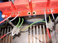
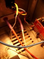
too thin wires
you need at least 2,5qmm for PSU
speaker GND return goes from PSU pcb ( star gnd) to speaker terminal - not from amp pcb , as you made
that's all I can see from these pictures
more , please
you need at least 2,5qmm for PSU
speaker GND return goes from PSU pcb ( star gnd) to speaker terminal - not from amp pcb , as you made
that's all I can see from these pictures
more , please
The amp board ground needs to go directly to the PS board ground. The chassis ground is strictly for safety, it has nothing to do with the operation of the amp. Get rid of the 1.8K thermisters.
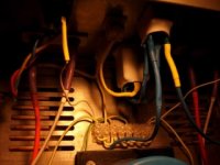
Change wire !
Hi Zen ,
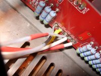
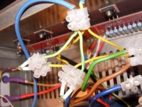
I changed the wire as suggested . Do you mean the ground in this photo....
from the amp board back to the PSU ?
Rich
PS heatsinks still cold !
Hi Zen ,
I changed the wire as suggested . Do you mean the ground in this photo....
from the amp board back to the PSU ?
Rich
PS heatsinks still cold !
Attachments

Last edited:
GND wire from PSU to pcb can be fairly thin , but all other wires must have decent dia
so - wires from PSU to pcb - + , gnd , -
from pcb to pos lsp terminal -
from PSU to neg spk terminal
now - tell us - what's input fashion ?
unbalanced ( RCA ) , balanced (XLR) or both ?
don't be shy with pictures ; we are working with them as much with your descriptions , or even more
so - wires from PSU to pcb - + , gnd , -
from pcb to pos lsp terminal -
from PSU to neg spk terminal
now - tell us - what's input fashion ?
unbalanced ( RCA ) , balanced (XLR) or both ?
don't be shy with pictures ; we are working with them as much with your descriptions , or even more
Now really confused !
Hi Bill ,
Is the 1.8k thermistor the wrong value ? am I to remove them from between the PSU pcb and the ground ? place them infront of the transfo feed ?
If I remove the ground from the amp board to the chassis I have no direct ground from ,either the PSU pcb or the amp board pcb .... ?
Pics for Zen , the input is balanced only
Attachments
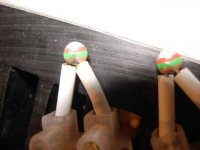
FLASH ooopS !
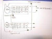
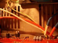
put the NTC before the transfo and ..... see pic - took them out completely .... Wired ground between amp board and power supply .... put NTC back across IEC chassis ground ... STILL NO HEAT
put the NTC before the transfo and ..... see pic - took them out completely .... Wired ground between amp board and power supply .... put NTC back across IEC chassis ground ... STILL NO HEAT
Attachments
Do you have the trafo center tap hooked to the PS ground? It won't work without it.
Those thermisters are so high in resistance that they really aren't providing any protection, but that is not the problem with the amp unless you somehow have them in the return path from the amp boards to the PS.
You definitely cannot use your 1.8Ks on the trafo primaries. CL60s are 10 ohms cold and rated at 5A. They should be used for the surge limiters and the ground isolation.
The chassis should be directly connected to the IEC ground lug.
Cheers Bill ,
trying to get the CL 60 here in the UK is impossible ... I have to order them from your yard through Digi Key ....
The problem is in the amp board . I have started checking all the values against the schematic .... none of the resistors are in the mix , the zena are spot on though ... the caps are hard to get to without taking the board of the sinks ...
any ideas ?
Rich
Farnell has them, I just looked. They have 276 of them in stock. Search for CL60.
Are you sure you have + and - 31v to ground on the amp boards?
Are you sure you have + and - 31v to ground on the amp boards?
Last edited:
- Status
- Not open for further replies.
- Home
- Amplifiers
- Pass Labs
- Complete Novice Needs Help