Thanks !
Maths and I are not lovers thats for sure ! I spent my teenage years on your side of the Atlantic where the pot was plentiful and cheep...and the girls loved my accent..... Boy, I regret it now .
I found a parts list here on the site with the Digikey stock number on it . Digikey use the same stock number here in their UK ..... 😀
I'm hoping my heat sinks are big enough to expand some day, especially as the top and bottom plate will be made from (anodised) 3mm St Steel . and the rear panel 2mm copper . I have those heat sinks from my little hick up . I could use one for the front plate . its looking kind of cool also .
I have also found a recipe for a thermal epoxy home brew . I have all kinds of metallic powders I can use , but bronze seems to be the best option , So 1:1 ratio ( mix ) join the side sinks to the front one and I'll be able to store ice cream in it .
Rich
Gents,
I got my Digikey order this morning and thought it would be a good idea to read what each item does within the circuit as I populate the boards.
TIA
I got my Digikey order this morning and thought it would be a good idea to read what each item does within the circuit as I populate the boards.
TIA
Maths and I are not lovers thats for sure ! I spent my teenage years on your side of the Atlantic where the pot was plentiful and cheep...and the girls loved my accent..... Boy, I regret it now .
I found a parts list here on the site with the Digikey stock number on it . Digikey use the same stock number here in their UK ..... 😀
I'm hoping my heat sinks are big enough to expand some day, especially as the top and bottom plate will be made from (anodised) 3mm St Steel . and the rear panel 2mm copper . I have those heat sinks from my little hick up . I could use one for the front plate . its looking kind of cool also .
I have also found a recipe for a thermal epoxy home brew . I have all kinds of metallic powders I can use , but bronze seems to be the best option , So 1:1 ratio ( mix ) join the side sinks to the front one and I'll be able to store ice cream in it .
Rich
I've never heard of this method, however one purpose of the pad is to electrically insulate the back of the mosfet from the heatsink. If your metal epoxy is conductive, I dont think it will work. Why not mica and thermal grease, or silpads?
Russellc
are there any notes on the above topic that could help ?
Yes, the F-5 manuals over on the Firstwatt site.
Russellc
Thank you Russell ,
I have the grease . I used the epoxy to join the heatsinks together ...
The zxt 450 I ordered have different lead dimensions than my PCB ... are they useless ?
I was full of confidence. This is going to be a lot more difficult than I thought ...
Rich
I have the grease . I used the epoxy to join the heatsinks together ...
The zxt 450 I ordered have different lead dimensions than my PCB ... are they useless ?
I was full of confidence. This is going to be a lot more difficult than I thought ...
Rich
Hi,
slide a tube insulator over the middle leg of the ZTX.
Look carefully at the ZTX datasheet and determine which leg goes into which hole of the PCB.
Form the legs into the arrangement needed and drop it in. Check you have no shorts even if the transistor body gets abused/moved at some time in the future.
Solder it in place.
are there any notes on the above topic that could help ?
Hi Rich,
from your first post I assume that you are building an Aleph 30. I don't know whether a construction guide for this amp is available. But anyway, I have some hopefully useful links for you:
For help in the correct identification of the ZTX legs (also in comparison to equivalent parts) and general assembly hints see cviller's F5 guide:
http://viller.eu/audio/2009jan_gbf5/gbf5_guide.pdf
You might also have a look at this F1 assembly guide for getting an overview on how to organize the building process:
F1 DIY Amp
Hope this helps
Last edited:
Thank you Russell ,
I have the grease . I used the epoxy to join the heatsinks together ...
The zxt 450 I ordered have different lead dimensions than my PCB ... are they useless ?
I was full of confidence. This is going to be a lot more difficult than I thought ...
Rich
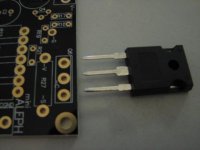
Dont lose confidence now, it really is a fairly straight forward build. Look at my posts when I was building it, If I made it through you will too! It was my first real SS build. What kind of fets do you have? Any pics? I'll be glad to post pics of what I've got. Keep on building!😀
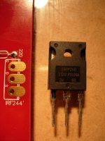
Here's a pic of some fets I got from member Blues, another shot of them beside the tiny Paul Daniels boards for the F-5, and finally a closeup of the pad on the Daniels board. Hope this helps.
Attachments
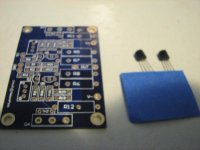
Whoops, that's for the F-5. I'm also building an Aleph mini. If it really trips my trigger, I've got the boards for the 30 or 60. doesnt appear any worse than the F-5, plenty of support here.
Russellc
Russellc
Hi Russell ,
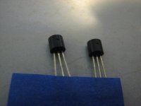
DiodesZetex | Semiconductors | Discretes | General Purpose Transistor | NPN Small Signal |ZTX450
this is what I got ....
except the holes on the pcb are 3mm centres . I can't find anything to fit properly ... Is the pcb wrong ?
RuF
DiodesZetex | Semiconductors | Discretes | General Purpose Transistor | NPN Small Signal |ZTX450
this is what I got ....
except the holes on the pcb are 3mm centres . I can't find anything to fit properly ... Is the pcb wrong ?
RuF
Russell ,
this is what I have !
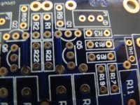
It looks like it fits, pin spacing appears to be the same, or is it just the pic?
Do you mean that the three pins match the 3 holes, but the fet isnt oriented correctly?
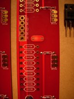
If so, of course the pins can be bent to suit, again a pic of the f-5, with pins bent at 90 degrees:
Dont be afraid to bend the pins a little, but watch stress and strain on those joints, particularly when tightening them down. Also, there is nothing wrong with attaching them from short wires going from the mosfet to the board.
Attachments

Last edited:
Looking at your pics again, it does appear the holes are not quite wide enough for the fets pins.....wires should fix that. Remember, those fets are very sensitive to static.
Russellc.
Russellc.
I really appreciate all your help Russell ..... I just realized we're brothers from Speaker world
cheers RuF
cheers RuF
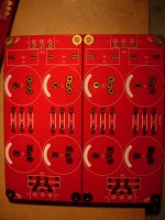
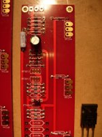
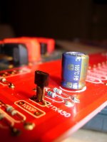
is this ok ?
Looks good...is that tape or something wrapped around the center leg?
If they arent touching I wouldnt worry about it, tape (if that's what it is) may be conductive. Or maybe I just cant see! Appears you've just spraddled the legs out on the sides to fit the holes. Should be fine, I just dont know what the "tape" is!
Russellc
Ok I'll remove it ... thanks
As long as the legs dont touch it shouldnt be a problem.
Russellc
- Status
- Not open for further replies.
- Home
- Amplifiers
- Pass Labs
- Complete Novice Needs Help