Hi Bill,
the sinks are .... 165 h x 430 l x the fins 75 mm on a 15 mm base .
the internal dim between sinks is 300 mm . Rear panel 1.6 mm st/st . top and bottom panel 3mm st/st with 21 no 60 x 6 mm slots each side top and bottom . 12 mm anodised front plate when I can afford it .
The transfo are 125 dia .... I was thinking of mounting the psu vertically on the back of the front plate ? this way I can get an decent amount of space between the AC components and at the same time run all AC signal front to back in the centre .
The whole cabinet is one big HEAVY heat sink
The internal finish for fets still needs some work ... 1200 grit wet and dry so far and will be using Silpads .
Those are big heatsinks, they should be able to handle 150 watts a piece. You should be able to crank the bias up considerably if you choose, as long as you have good heat transfer from the fets.
I also mount the trafos in the front of the chassis, and keep the inputs to one side and the AC inlet and wiring to the other side, but I have always used BrianGTs boards that have separate output boards for the fets, quite a bit different than yours. Make sure you twist the AC wire runs and don't run any amp wiring in parallel with any AC power wiring unless it is a good distance away.
That will be a very substantial chassis.
Screwing
Gents,
I have 2 types of fixings for the fets ! Stainless and Nylon . Which would be best suited ?
TIA , Rich
Gents,
I have 2 types of fixings for the fets ! Stainless and Nylon . Which would be best suited ?
TIA , Rich
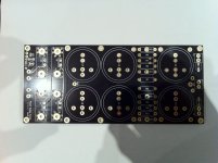
chipamp.com power supply PCBs
Just to tie off my power supply PCB enquiry (post 48), I got my boards from chipamp.com and they are a thing of beauty - gold plated holes on a black board. I've attached a photo, I hope it attaches ok.
The board is dual polarity, has space for 6 big caps, two snubber caps, resistors to place between capacitor stages and drain resistors. Size is 88x202 mm^2, 8 inches x 3.5 inches.
Thanks Bill and Dennis
Steve
Attachments
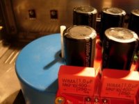
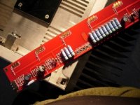
Looking really tight, actual mirror finish on the heatsinks, I thought that was a figure of speech😀
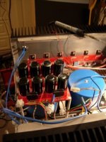
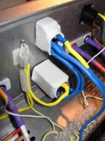
Audio signal wiring ?
Hi Gents ,
I need help with the wiring please ...
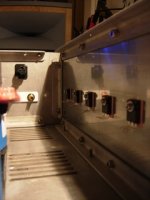
Bottom left hand side ..... IN ... is this the signal from my XLR ?
Middle centre , this must be the input from the PSU and the output to the binding post .... which is which ?
thank you for your patience , Rich
Hi Gents ,
I need help with the wiring please ...
Bottom left hand side ..... IN ... is this the signal from my XLR ?
Middle centre , this must be the input from the PSU and the output to the binding post .... which is which ?
thank you for your patience , Rich
Attachments
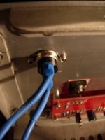
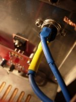
I looked at your previous pic, yes, thats the xlr connections.
1 is ground, 2 is the plus input, 3 is the minus input.
The PS hookup is self explanitory.
Output goes to the red post, the other goes to the black post
1 is ground, 2 is the plus input, 3 is the minus input.
The PS hookup is self explanitory.
Output goes to the red post, the other goes to the black post
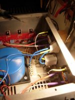
5 fuses WTF ?
Hi Gents,
now Im completely frustrated .... I have blown 5 fuses , checked ,double checked , triple checked .
I had no problems when using one transfo for testing ,but as soon as I add the other ..... fizz ,boom , bah , bollocks .....
Is there anyone in London that can spare the experience and time to pull this amp back from the skip ?
Rich
Attachments
You gotta give us a lot more info.
Are you using dual supplies, one for each channel, or did you parallel the secondaries.
How big are the trafos and how big are the fuses.
Did you use CL60s for turn on surge.
Can you make a sketch of the PS wiring.
You should disconnect the amp boards until you get the PS sorted.
Are you using dual supplies, one for each channel, or did you parallel the secondaries.
How big are the trafos and how big are the fuses.
Did you use CL60s for turn on surge.
Can you make a sketch of the PS wiring.
You should disconnect the amp boards until you get the PS sorted.
Hi,
you should use a mains light bulb tester to save the cost of the fuses and to allow you to take some voltage measurements of the faulty equipment without damaging any components.
I re-powered an amp that had the output to rail diodes in place and had swapped the -ve & +ve PSU leads. The Bulb lit! I started measuring and found +-0.8Vdc across the PSU. What the F...? Then it dawned.
OK !
Andy , Bill thanks for the help !
Just bought 5 more and blew 4 left 🙂
I tried with transfo wired together ... nothing else -it blew
IEC (fused) wired to toggle switch . From top of toggle wire goes to thermal cut
off , to next thermal cut off and then to yellow transfo mains and back to toggle .
The 2 transfo are wired as per info on side ..... Sec 1 ,red and green blue and brown .... on both
Attachments
Sorry Bill ,
the primary winding is 230 v 50 htz ... 300 va
secondary windings are 21 v 7.1 amps
Rich
the primary winding is 230 v 50 htz ... 300 va
secondary windings are 21 v 7.1 amps
Rich
If each trafo works hooked up alone, and it blows fuses when both are connected then the fuses are too small, I would think, unless you have a bad wiring mistake.
The turn on surge of 2 trafos can be pretty substantial, that's why the CL60 thermisters are generally used, one on each leg for 240V. 3 or 4A slow blow fuse would be the minimum, what are you using?
It would be helpful to sketch your PS and post it. Just looking at that might help you.
As Andrew said, a lightbulb in series with the power cord is a handy item in these cases. I made up a short cord with two outlets in series so I can plug a lamp in one and an amp in the other.
Last edited:
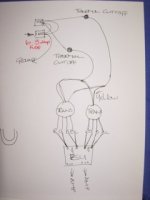
Hi Bill ,
Ill pick up a light fitting in the morning .... heres a sketch
BTW there is a thermistor between the AC inlet and the chassis ground .... the fuse is 6.3 amp !
Ill pick up a light fitting in the morning .... heres a sketch
BTW there is a thermistor between the AC inlet and the chassis ground .... the fuse is 6.3 amp !
Attachments
Last edited:
Bill,
the NTC I used is 1.8k @ 20 degrees .... but I only have one as I said between inlet and
ground ... You suggested one on each leg ,would you have time to do a quick sketch for me ?
Rich
the NTC I used is 1.8k @ 20 degrees .... but I only have one as I said between inlet and
ground ... You suggested one on each leg ,would you have time to do a quick sketch for me ?
Rich
Hi Rich
your sketch is a little hard to read, but it looks as if the fuse is across the two input AC lines(??) Am I reading this right? That arrangement would immediately blow the fuse, it should go live connector - fuse - transformer primary wire - second primary wire - neutral connector. Sorry if I misread.
Steve
From what I can see of your PS boards they are using 2 small bridges in parallel instead of 1 big one. Can you confirm that? If that is the case you need to do a little more wiring. Regardless of that, the secondaries are directly shorted anyway.
Remove all the trafo secondary leads from the boards and separate them.
On each trafo, find the pairs that measure 21v, tape them or put wire nuts on the ends, and tape them together.
On one trafo, connect one wire from each pair together, then measure across the 2 remaining wires. If you measure 42v or so then you have the correct wires connected together. That is your center tap that goes to the board ground. If you have close to 0v across the 2 wires instead of 42v then the secondaries are out of phase and you must reverse the wires of one of the secondaries. Don't hook up the boards until you have this sorted out.
- Status
- Not open for further replies.
- Home
- Amplifiers
- Pass Labs
- Complete Novice Needs Help