Keep in mind that the piezo output is proportional to cone acceleration. The coil current is (crudely) proportional to cone velocity.
Velocity and acceleration are two fundamentally different things. They cannot possibly match over any significant range of frequency - they inherently have quite different phase and frequency responses.
I am pressed for time and can't go into any more detail here. But the only way I know of, to deeply understand this stuff, is to learn complex number arithmetic, and how to describe transfer functions in terms of complex number polynomials. Without that, all we've got is words, and words don't do very well at accurately describing complicated technical concepts.
-Gnobuddy
If only we could work in Euler's Identity into the matrix algebra required to solve the complex polynomials and come up with an op amp circuit to solve them...😀
Superficially I understand the acceleration velocity concept but in my dumbed down way I think the cone is always accelerating and the piezo output looks a lot like the sine wave I am feeding into the system. Further, in my Piezo for Dummy's concept, if the phase shift were zero, the MFB should be as simple as looking at the difference in the instantaneous voltage of the input signal and comparing that to the instantaneous voltage of the piezo, then using a difference amp to instantaneously boost the input signal so the woofer is driven to the level it should be to duplicate the original input - if that makes any sense.😕
Its just that this mechanoelectrical system is inducing phase shift...I think that's the only problem.
This may be blasphemy from an ignoramus but to me, looking at the output of the MFB I think it is just acting as a voltage divider, feeding back a bit to the mixer. One way maybe to test this is get simultaneous reads across the MFB resistor and woofer?
Thanks again for all your input!
That is quite possible, but it does not mean that velocity and acceleration are the same thing - they aren't! 🙂During some time, french manufacturer Cabasse made servoed loudspeakers with a combinaison of feedbacks from a velocity bridge and from a piezo acceleration sensor.
-Gnobuddy
Hey, I like Euler's Identity! 😀
Suppose you feed a sinewave signal to the speaker. Let's say your speaker cone position is then represented by the sine wave: x=A sin (wt)
The speaker cone velocity is the first time derivative of the position. Two uber-geniuses (Leibniz and Newton) told us how to find a formula for this velocity: v = A w cos (w t).
Notice three things about this velocity formula:
Now, let's take one more step, this time, calculating the cone acceleration: a = -A w^2 sin (w t).
More things to notice, this time about the acceleration:
That can of worms having been dealt with, we now open a bigger can of nastier worms: how is the cone position of a loudspeaker related to the voltage you apply to drive it?
This time I really can't even begin to explain it without complex number arithmetic. But, at low frequencies around the woofer resonance, the nutshell version is that there are dramatic changes in both amplitude and phase as you sweep the drive frequency from below, to above, the fundamental mechanical resonance of the speaker. Well below resonance, the cone acceleration (which is proportional to emitted SPL) falls off at -12 dB/octave. Well above resonance, cone acceleration is constant, flat with frequency.
As you traverse this frequency range, there will be a constantly changing amount of phase, adding up to 180 degrees of phase shift in total.
Now, there is no way to beat any of this! Nature does what nature does, and we have no choice about it. You will experience at least 180 degrees of phase shift in your piezo signal as you traverse the resonance frequency of the driver.
At least? Yup - so far we're only talking about a driver in a sealed box. If the box has a port, things only get even more complicated (and harder to predict).
Things also get more complicated as you go up to much higher frequencies, and the cone begins to experience break-up. But let's leave that third (and even bigger) can-o-worms for later!
You are quite right about the very broad details: get some sort of signal that tells you what the speaker does, feed it back to the input, and hey presto, a better woofer! 🙂
Unfortunately, this is one of those cases where nature doesn't make it easy. The devil really is in the details - in this case, the details of phase and amplitude response of the system.
So, to get anywhere, that's where you have to start - with good amplitude and phase measurements through the entire frequency range from, say, 10 Hz to 5 kHz.
Back when I worked on my MFB system, all I had to do was hook up one of my employers audio measurement systems. You probably don't have that luxury, so you may need to download and run appropriate software; you may also need to come up with suitable electronics to mate the woofer and piezo signal to your computer's sound card.
Mercifully, these days, there is free software that does this sort of thing. So at least you don't have to shell out thousands of dollars just to get measurement software, like the bad old days of 1998! 😱
-Gnobuddy
Yes to both, but there is more to it!...I think the cone is always accelerating and the piezo output looks a lot like the sine wave I am feeding into the system.
Suppose you feed a sinewave signal to the speaker. Let's say your speaker cone position is then represented by the sine wave: x=A sin (wt)
The speaker cone velocity is the first time derivative of the position. Two uber-geniuses (Leibniz and Newton) told us how to find a formula for this velocity: v = A w cos (w t).
Notice three things about this velocity formula:
- First, the amplitude has changed (it's multiplied by w, the angular frequency.)
- Second, it is now a cosine wave, rather than a sine wave. A cosine looks exactly like a sine on an oscilloscope - but it is actually shifted by 90 degrees from a sine.
- Third, the amplitude is now proportional to frequency. It increases linearly as the frequency increases.
Now, let's take one more step, this time, calculating the cone acceleration: a = -A w^2 sin (w t).
More things to notice, this time about the acceleration:
- There is a (-) sign in front. This means there is a 180 degree phase shift between acceleration and position.
- The amplitude is different yet again, because of the w^2 term.
- This also means amplitude rises strongly with frequency.
That can of worms having been dealt with, we now open a bigger can of nastier worms: how is the cone position of a loudspeaker related to the voltage you apply to drive it?
This time I really can't even begin to explain it without complex number arithmetic. But, at low frequencies around the woofer resonance, the nutshell version is that there are dramatic changes in both amplitude and phase as you sweep the drive frequency from below, to above, the fundamental mechanical resonance of the speaker. Well below resonance, the cone acceleration (which is proportional to emitted SPL) falls off at -12 dB/octave. Well above resonance, cone acceleration is constant, flat with frequency.
As you traverse this frequency range, there will be a constantly changing amount of phase, adding up to 180 degrees of phase shift in total.
Now, there is no way to beat any of this! Nature does what nature does, and we have no choice about it. You will experience at least 180 degrees of phase shift in your piezo signal as you traverse the resonance frequency of the driver.
At least? Yup - so far we're only talking about a driver in a sealed box. If the box has a port, things only get even more complicated (and harder to predict).
Things also get more complicated as you go up to much higher frequencies, and the cone begins to experience break-up. But let's leave that third (and even bigger) can-o-worms for later!
You are quite right about the very broad details: get some sort of signal that tells you what the speaker does, feed it back to the input, and hey presto, a better woofer! 🙂
Unfortunately, this is one of those cases where nature doesn't make it easy. The devil really is in the details - in this case, the details of phase and amplitude response of the system.
So, to get anywhere, that's where you have to start - with good amplitude and phase measurements through the entire frequency range from, say, 10 Hz to 5 kHz.
Back when I worked on my MFB system, all I had to do was hook up one of my employers audio measurement systems. You probably don't have that luxury, so you may need to download and run appropriate software; you may also need to come up with suitable electronics to mate the woofer and piezo signal to your computer's sound card.
Mercifully, these days, there is free software that does this sort of thing. So at least you don't have to shell out thousands of dollars just to get measurement software, like the bad old days of 1998! 😱
-Gnobuddy
They are'nt but are mathematically related (instantaneous acceleration being the derivative of velocity, dv/dt).That is quite possible, but it does not mean that velocity and acceleration are the same thing - they aren't!
IDEA
To counteract the varying phase issue mentioned, how about introducing a Variable Phase Filter circuit into the mix.
I know at least one person thinks things like that are evil 😀 but if used correctly they are NOT !
To counteract the varying phase issue mentioned, how about introducing a Variable Phase Filter circuit into the mix.
I know at least one person thinks things like that are evil 😀 but if used correctly they are NOT !
forr - agreed, now I understand that we're on the same page (see my previous post, #583). I wasn't sure before, from your previous post.They are'nt but are mathematically related (instantaneous acceleration being the derivative of velocity, dv/dt).
There is already some confusion on this thread about velocity and acceleration being the same thing. So I wanted to make sure that you/I didn't add still more confusion! 🙂
-Gnobuddy
Zero D, I think every young engineer has that thought when she starts to engineer her first servo feedback system. 🙂To counteract the varying phase issue mentioned, how about introducing a Variable Phase Filter circuit into the mix.
It is certainly possible to have some phase compensation in the system, in addition to the integrator already mentioned. In fact there has been some discussion about additional filtering - bolserst talked about using notch filters to remove cone breakup resonances, and I talked about using a Chebyshev filter to provide a little better gain and phase margin around the unity-gain-frequency of an MFB system I built many years ago.
The trouble is that every circuit (including all-pass filters) adds some time delay to the signal, so that in the end, when the frequency is high enough, there always even more phase lag than there was without the all-pass filter. Because of this, I don't think it is possible to compensate for the phase reversal in the woofer using an all-pass filter.
But let's not lose sight of the forest for staring at too many trees - the fact of the matter is that it is quite possible to get a decent MFB system using nothing more than a single integrator in the forward signal path. It's not trivially simple, sure, but it's not too complicated, either.
Beyond that simple integrator, you have to add more and more additional complications to get smaller and smaller improvements in performance. That may be worth doing, especially for us enthusiastic amateurs (who don't have deadlines and accountants to answer to). But, IMHO, the first step is to get the basic system up and running...and all that takes is an integrator in the forward path!
-Gnobuddy
Sure, why not? If it's not utterly ridiculous (like mining green cheese from the moon ridiculous), it's probably worth simming! 🙂Well i think it's worth trying, or at least simming 😉
I don't know about other sims, but the one I use (LTSpice) is very poor about predicting instability in a circuit. In fact, I have designed Wien-bridge audio oscillators in LTSpice, only to find they won't oscillate in the sim!
After much head-scratching, I found that I have to add an additional "kick" from a separate voltage source (set to produce a short pulse or a few cycles of small-amplitude sine wave of about the right frequency) to get oscillations to start in the simulator.
In real life, the same oscillator started perfectly on it's own, thanks to real-world noise and interference that is not included in the simulated world of LTSpice.
So there is some chance that LTSpice will produce a stable MFB speaker simulation, where the real-world thing will actually be unstable...I don't trust LTSpice on this particular point, though it's a wonderful tool in many ways.
Why not? I've taught over twenty-five women engineering students in just the last few years alone. Yet, the public image of an engineer is almost always male. Little girls usually don't even realize that they could grow up and become engineers if they want to. That needs redressing, don't you think? 🙂What's all the SHE business ?
-Gnobuddy
@ Gnobuddy
I don't have a problem if you think it's utterly ridiculous, others may not 😉
I don't have a problem with girls in engineering either, in fact the more the better 🙂 It just sounded as if you were inferring that to me, for some unknown reason. I take it now you weren't, so no problemmo.
I don't have a problem if you think it's utterly ridiculous, others may not 😉
I don't have a problem with girls in engineering either, in fact the more the better 🙂 It just sounded as if you were inferring that to me, for some unknown reason. I take it now you weren't, so no problemmo.
Suppose you feed a sinewave signal to the speaker.
Let's say your speaker cone position is then represented by the sine wave: x=A sin (w t)
The speaker cone velocity is the first time derivative of the position.
Two uber-geniuses (Leibniz and Newton) told us how to find a formula for this velocity: v = A w cos (w t).
Notice three things about this velocity formula:
So, (a) an oscilloscope is a poor tool for studying absolute phase, and (b) velocity has a 90 degree phase shift compared to position, and (c) cone velocity has a different frequency response than cone position.
- First, the amplitude has changed (it's multiplied by w, the angular frequency.)
- Second, it is now a cosine wave, rather than a sine wave. A cosine looks exactly like a sine on an oscilloscope - but it is actually shifted by 90 degrees from a sine.
- Third, the amplitude is now proportional to frequency. It increases linearly as the frequency increases.
Now, let's take one more step, this time, calculating the cone acceleration: a = -A w^2 sin (w t).
More things to notice, this time about the acceleration:
Okay, so far we've determined that cone position, cone velocity, and cone acceleration all look sinusoidal on a 'scope. BUT, they are all phase shifted with respect to each other. AND, they all have different frequency responses!
- There is a (-) sign in front. This means there is a 180 degree phase shift between acceleration and position.
- The amplitude is different yet again, because of the w^2 term.
- This also means amplitude rises strongly with frequency.
Excellent pedagogy! Must read!
say cone position = A sin (w t),
with A being the Amplitude of the motion,
with w being the omega pulsation (frequency * 2 * pi),
and t being the time variable,
then cone velocity = A w cos (w t),
then cone acceleration = -A w^2 sin (w t)
with A being the Amplitude of the motion,
with w being the omega pulsation (frequency * 2 * pi),
and t being the time variable,
then cone velocity = A w cos (w t),
then cone acceleration = -A w^2 sin (w t)
There is no better explanation, indeed. Let me congratulate Gnobuddy for not saying that "acceleration advances velocity by 90 degree". Indeed, electrons can't predict the future. Use a velocity signal that's not sinusoidal, say a triangular waveform. You'll see that the corresponding acceleration signal isn't anymore a triangular waveform. Once for all, you'll realize that acceleration is the time derivative of velocity. Just what Gnobuddy explains.
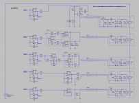
Cabasse VTA series if I remember. I sketched something like this on diyAudio on post #38 on http://www.diyaudio.com/forums/solid-state/166061-philips-motional-feedback-mfb-4.html#post4909822.During some time, french manufacturer Cabasse made servoed loudspeakers with a combination of feedbacks from a velocity bridge and from a piezo acceleration sensor.
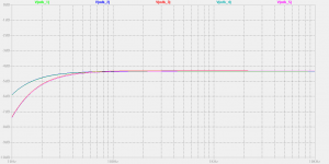
20 dB feedback at 100 Hz (distortion divided by 10 at such frequency)
12 dB feedback between 54 Hz and 195 Hz (distortion divided by 4)
6 dB feedback between 35 Hz and 360 Hz (distortion divided by 2)
Using a Vifa P17WJ-00-08 speaker that's exhibiting no cone breakup, the frequency response could fit into a 2 dB corridor from 12 Hz to 1700 Hz. This will be hard to measure, as practically nobody owns a calibrated measuring mike able to cope with such level of performance.
For not exceeding the Xmax of the speaker, you need an adaptive (variable cutoff frequency, from 20 Hz to 100 Hz) 2nd-order highpass filter governed by a cone instantaneous excursion estimator, that can be a time integrator hooked on the velocity signal.
In the context of an extreme-quality 2-way bookshelf speaker, there is a good match possible with one of those 800 Hz capable dome tweeters from TangBand having a rear chamber. Max height 33 cm (Ikea Kallax series).
What kind of 8-pin opamp would you recommend?
What kind of power amplifier would you recommend? A Kuroda structure, having a 8-pin opamp as front-end?
BJTs, lateral MOSFETs or vertical MOSFETs as power output devices?
Class-A, non-switching class AB, conventional class AB?
Crossover can be a passive Linkwitz-Riley 4th-order.
The woofer and tweeter phases will be synchronous, however the global phase will be damaged (distorted). Consequently, the polar diagram will be good, however the impulse response won't be good.
Crossover can be an active Linkwitz-Riley 4th-order.
Two power amplifiers.
The woofer and tweeter phases will be synchronous, however the global phase will be damaged (distorted). Consequently, the polar diagram will be good, however the impulse response won't be good.
Crossover can be digital, basing on two FIR filters.
Two power amplifiers.
The slopes can be anywhere between 3rd-order and 4th-order, the woofer and tweeter phases will be synchronous, and the global phase will be preserved. Consequently, the polar diagram will be good, and the impulse response will be perfect.
Anybody wanting to experiment this with me?
Attachments

Last edited:
Ah, I see where this is going. Curiously, it goes back to the very thing I've been harping on all along: goals. Different MF concepts are differentially suitable (by Leibniz or by Newton) to different parts of the sound compass. At higher frequencies, to obliterate hearable distortion. At lower frequencies, to obliterate the large resonance, without cutting distortion all that dramatically.Cabasse VTA series if I remember. I sketched something like this on diyAudio on post #38 on http://www.diyaudio.com/forums/solid-state/166061-philips-motional-feedback-mfb-4.html#post4909822.
20 dB feedback at 100 Hz (distortion divided by 10 at such frequency)
12 dB feedback between 54 Hz and 195 Hz (distortion divided by 4)
6 dB feedback between 35 Hz and 360 Hz (distortion divided by 2)....
Indeed, if you wanted to make an extremely great two-driver little box, you might do just what steph_tsf has explained as the Cabasse approach. I never think about MF except for subs, but I see how Cabasse (and some of the wise persons on this thread) might think about producing great sound north of 120 Hz.
About Hombre's experiments with a piezo gizmo, might be great fun experimenting with a 10-cent crystal to make a $200 driver sound better (or if you are Philips, to make a $20 driver sound better). But in the DIY world, why not get an ACM accelerometer with spectacular specs for $25 on eBay?
Not easy to work with piezo crystal because of the challenging parameters involved. The device has very large resistances and impedances which might slip hither and yon with frequency. Then you are playing the crystal into a device with an input impedance that may be hard to characterize too. Phase on an oscilloscope doesn't need much prodding to start wandering about. Which what I think Hombre might be finding as an artefact of measurement.
Ben
Not at all, I absolutely don't think it's utterly ridiculous. I think it's an excellent hypothesis - an untested idea, but a perfectly good one. Then, you "throw it at the wall and see if it sticks", as one colourful Australian put it. In other words, test the hypothesis (by simulation and/or actual experiment) to see if it actually works, or not. Nature has a way of letting inconvenient facts ruin perfectly good hypothesis, to misquote some famous person. 😀@ Gnobuddy
I don't have a problem if you think it's utterly ridiculous, others may not 😉
In this case, this particular hypothesis has occurred to lots of smart young engineers, so it has been tested - many times - in the past. I had exactly the same idea myself once, in my early twenties, when I first came up against a rather complicated servo system (it was used to accurately stabilize the frequency of a laser). My idea didn't work, and ended up in the idea scrapyard.
But IMHO it's still worth testing, or at least simulating - firstly as a learning tool, and secondly because it's always possible you're visualizing something new and different, and it will actually work.
My earlier comment about mining the moon for green cheese was just a joke, but with a grain of truth: there are some hypothesis that are really not worth the time and effort it takes to test them. For example, suppose I make the hypothesis that cardboard has a higher tensile strength than steel - that's absolutely not worth testing, unless I happen to be five years old, and a kindly nearby adult suggests I do the test and learn for myself that steel really is stronger than cardboard.
IMO, on this forum, the hypothesis not worth testing are things like the fairly frequent claims about expensive capacitors that magically sound better than cheaper capacitors, even though there is no measurable difference, and the listening tests were conducted in such a way as to make them utterly worthless.
I agree, the world definitely needs more women engineers, for a variety of reasons - all off-topic here, so I won't start on them!I don't have a problem with girls in engineering either, in fact the more the better 🙂 It just sounded as if you were inferring that to me, for some unknown reason. I take it now you weren't, so no problemmo.
And no, I made no assumptions about your gender - my apologies if you thought I did!
-Gnobuddy
Use a charge-mode amplifier, and all the big piezo-related problems seem to just go away. At least, they did for me. 🙂The device has very large resistances and impedances which might slip hither and yon with frequency. Then you are playing the crystal into a device with an input impedance that may be hard to characterize too.
-Gnobuddy
Thanks, Stephen! I appreciate the comment!Excellent pedagogy! Must read!say cone position = A sin (w t) waveform.
As Stephen points out, those three equations apply to anything moving in a perfectly sinusoidal way. For example, the movement of a piston inside a running car engine, if we neglect some relatively minor geometric effects from the angles of the piston-rods (connecting rods in British English).
So, in a way, these three equations actually don't even begin to touch the specific problem of how to make an MFB speaker system. They just discuss sinusoidal motion in general!
To start on the MFB woofer problem, we have to open the second can of worms: if the driving voltage applied to a speaker is Vp sin (wt), then the actual speaker cone position is not just "A sin (wt)"!
Instead, "A" is now itself a function of frequency, A(w). And there is additional phase shift too, also a function of frequency.
Figuring out A(w), and the corresponding phase phi(w), is where the complex number arithmetic comes in. You can also figure it out with masses, springs, shock absorbers, Newton's equations of motion, and calculus. Either way, it is not super-simple. And I can't find any way to really make it super-simple, short of saying "This is how it is!", which really doesn't help very much!
But, for what it's worth, this is how it is: the cone *position* acts like a 2nd-order lowpass filter; the cone *velocity* acts like a bandpass filter, with 6 dB/octave slopes on both sides of the woofer resonance frequency; and the cone *acceleration* acts like a 2nd order highpass filter, as I mentioned in this thread many posts ago. And the SPL is proportional to the cone acceleration, at least over the frequency range we care about for an MFB system.
And, yes, there is an additional 180 degrees of phase shift in the *cone position* as you sweep the frequency through the woofer resonance. This extra phase shift carries over to the cone velocity and cone acceleration, too. All of them have a 180 degree phase change as you go through the resonant frequency.
But it's not necessary to actually understand all this if the goal is only to make one MFB woofer for oneself. All it takes is a good accurate sweep of amplitude and phase (from the piezo sensor)...and the help of some of the people here who do know how to go from transfer function to MFB speaker. 🙂
-Gnobuddy
But it's not necessary to actually understand all this if the goal is only to make one MFB woofer for oneself. All it takes is a good accurate sweep of amplitude and phase (from the piezo sensor)...
Yes, one more final very good point. Many of the issues a commercial manufacturer has to sweat aren't important to a DIY adding MF to their system. Once again, contrasting views of how to proceed with real engineers on one side and DIYers on the other, with both sides being legitimate.
Ben
Yes, piezo crystals require the kind of buffering you indicate.Use a charge-mode amplifier, and all the big piezo-related problems seem to just go away.
The problem is (or was) why Hombre was getting inexplicable phase results with his breadboard circuit. That, I was suggesting, could be because you can't just plug a piezo crystal into a 'scope input without buffering. 'Scopes don't have terribly high input impedances. A 10X probe might help and good ones are very carefully compensated for frequency.
But even with buffering, challenging to do audio design with high impedance devices for a bunch of reasons, unless they are integrated units like the accelerometers.
Question about acceleration vs velocity sensing: is one more susceptible to artifactual pick-ups than the other? Like box or floor vibrations, non-axial cone motions, etc?
B.
The good old ACH-01 needs full eletrostatic shielding to be free from any disturbance, that's what I found (and I seem to recall others reporting this). The best way would seem to be using full shielding and putting the charge amp right at the crystal (a few small SMD parts not contributing to any significant mass increase. Or you could make this part of the seismic mass).But even with buffering, challenging to do audio design with high impedance devices for a bunch of reasons, unless they are integrated units like the accelerometers.
Question about acceleration vs velocity sensing: is one more susceptible to artifactual pick-ups than the other? Like box or floor vibrations, non-axial cone motions, etc?
On the second topic, I have no clear answer. I would suspect no difference except for severe parasistic effects that pick up unrelated movements in different amounts.
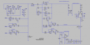
There is the post #35 on http://www.diyaudio.com/forums/solid-state/166061-philips-motional-feedback-mfb-4.html#post4909822 about this.Use a charge-mode amplifier, and all the big piezo-related problems seem to just go away. At least, they did for me.
Perhaps you will recognize the MFB_4 section as the charge-mode amplifier, with X400 as opamp, and X401 as acceleration-to-velocity converter (a time integrator).
The velocity output only serves for checking the time integrated piezo output (supposed to be cone velocity), against a Voight bridge output (also supposed to be cone velocity).
All opamps need to be TL071 or TL072 opamps. They feature JFET inputs exhibiting very low polarization currents, and very high internal impedances.
I made the assumption that the piezo disc exhibits a 2 nF capacitance. Such order of magnitude should be valid for the tiny 3 x 3 mm piezo square used by Philips inside the RH532 MFB, RH541 MFB, RH544 MFB, RH544 MFB, RH545 MFB etc.
One should experimentally determine if a 15 mm piezo disc exhibits a significantly large capacitance, say 10 nF or more.
You will recognize the MFB_5 section as the plain voltage mode.
The piezo element is loaded it by a 10 meg ohm resistor followed by an opamp (X500) used as high impedance voltage follower.
Let me suggest a measurement procedure, relying on such interface.
Gently apply a 50 Hz frequency to the woofer, coming from a sinus generator and a power amplifier. Adjust the signal amplitude, for the woofer cone to move back and forth by 1 millimeter or so, no more. Our measurement is not supposed to be destructive.
Using a single trace scope, observe the voltage that's delivered by the opamp. Take notice of the amplitude.
Say you are getting a 100 mV peak-to-peak amplitude at the opamp output.
Now change the resistor that's loading the piezo. Progressively reduce its value to 2.2 meg, 1.0 meg, 470k, 220k, 100k, 47k. Observe the opamp output amplitude. It should progressively reduce.
Having seen this, let's try quantifying the measurement.
From your E12 series resistor stock, select the loading resistor that's causing a 3 dB amplitude reduction, in other words, select the loading resistor that's determining a 71 mV peak to peak amplitude at the opamp output (in case it was 100 mV beforehand).
Say this is a 180k resistor.
It follows that the impedance (of capacitive nature) of the piezo also equals 180k at 50 Hz, albeit phase shifted by 90 degree, compared to the impedance of the 180k resistor (of resistive nature).
The 90 degree impedance phase mismatch explains why the attenuation is 3 dB instead of some expected 6 dB.
We know that the impedance (capacitance) module equals 1 / (6.28 * F * C). Thus, C equals 1 / (6.28 * 50 Hz * 180k ohm).
Thus C equals 17.7 nF.
This is the capacitance of the 15 mm piezo disc.
This is of importance in case you want to experiment with a charge-mode amplifier. This is the MFB_4 section, with X400 as opamp. You can design the charge-mode amplifier, so it provides an almost 0 dB voltage gain for the audio frequencies. The feedback capacitor (C401) shall thus be of same size as the piezo capacitance. Say a 18 nF capacitor in practice, here. Unfortunately, R402 (1 meg ohm) must be there for providing a DC path to the opamp input. This reduces the opamp output below 10 Hz or so. Globally, this is like loading the 17.7 nF capacitance by a 1 meg ohm resistor, without needing to deploy a high impedance link between the piezo sensor and the opamp. There will be less hum pickup. Such is the advantage of this circuitry.
And possibly, because such circuitry is exploiting the piezo current (instead of the piezo voltage), there may be more benefits that I'm not aware of. Sinking the piezo current may internally damp it like when sinking the current generated by an electric motor acting as brake.
Okay, there is still a 1 meg ohm resistor (R402), but being mounted a few millimeters away from the opamp, it won't pickup hum.
And, you always can try a 2.2 meg resistor (R402), or possibly a 4.7 meg resistor, for extending the MFB low frequency action down to 5 Hz or possibly 2.5 Hz.
Attachments
Last edited:
- Home
- Loudspeakers
- Subwoofers
- Commercial motional feedback woofer available sort of