What you call "an integrator with gain" is an equalizer, boosting the low frequencies. Such boost is required for compensating the 1st-order highpass filter formed by the 440 kilo ohm impedance that's loading the 38 nF piezo sensor capacitance.
This report looks at the output and phase (by eye) of the piezo (now with elegant seismic mass added) and compares it to a NEW reference point - the output (pin 1) of op amp IC104 (1/2) - which I see as going into the mixer op amp. The 'top' leg of the mixer would be this signal (IC104 pin 1 output), the bottom leg of the input to the mixer is where I would bring in the piezo output.
You know those braided wires in a cheap pair of headphones? - very tiny - I took an individual wire from that strand, pretty close to the diameter of a hair and soldered it to the output (pin 1) of op amp IC104 (1/2) so I could get a probe on it and look at output as a function of frequency (20-120 hz). I compare this to the output of a piezo signal conditioned by a summing / buffering amp to an integrator / bass boost circuit (same noisy breadboard circuit one I have been using and similar to one shown above in Steph_tsf's schematic - except I have a 33k resistor between 1st and second op amp.
I was going to just take voltage readings for both as a function of frequency but that was too time consuming / tedious so I tried to capture a sweep - I captured the essence -
Here are my observations -
1. the output from IC104 (YELLOW trace) rises a bit from 20-45, then back down..not too much maybe 30%.
2.the phase of the piezo (through the circuit) is in phase with IC104 from about 20-30 Hz, the slowly shifting, being about 180 degrees out of phase around 110 Hz.
3. The amplitude of the piezo output, as predicted rises from 20-about 60Hz, then tapers back down.
4. I dont see what the integrator / bass boost op am circuit is gaining me other than shifting the phase and adding noise.
See attached simultaneous sweep - look close you can see in phase waves at the beginning of sweep (20 Hz) and change in amplitude (mostly of piezo (BLUE trace) and phase with higher frequencies.

Last edited:
Hombre, this sort of sweep looks pretty, but is completely missing the phase information we need. It's also missing all the higher frequency data - the stock low-pass in the Sony electronics is preventing you from measuring all the way up to 5 kHz or so, which is where all the bad stuff (cone breakup, piezo sensor resonances, etc) hides.
I'll be up-front; I think there is zero chance that your piezo sensor will plug-n-play with the stock Sony electronics and actually produce any useful result. So you have come to a fork in the road: one road is to just bale on the whole DIY MFB idea, keep the woofer stock, and enjoy it as-is.
The other road is to toss all the stock Sony small-signal electronics, replacing it with your own. To build your own, you'll also need to get proper phase and gain sweep data. It is not by any means an impossible task, but it isn't a trivial one, either.
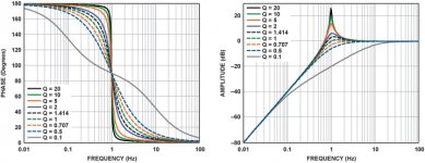
Let me start by attaching an image that will show you what it is you/we actually need from your woofer-piezo measurement. I grabbed this image off the 'Net; it shows gain and phase plots for a generic second-order high pass filter of varying Q. When you get a proper gain/phase plot of your woofer/piezo system, it will look a lot like one of the low-Q plots in this image.
-Gnobuddy
I'll be up-front; I think there is zero chance that your piezo sensor will plug-n-play with the stock Sony electronics and actually produce any useful result. So you have come to a fork in the road: one road is to just bale on the whole DIY MFB idea, keep the woofer stock, and enjoy it as-is.
The other road is to toss all the stock Sony small-signal electronics, replacing it with your own. To build your own, you'll also need to get proper phase and gain sweep data. It is not by any means an impossible task, but it isn't a trivial one, either.
Let me start by attaching an image that will show you what it is you/we actually need from your woofer-piezo measurement. I grabbed this image off the 'Net; it shows gain and phase plots for a generic second-order high pass filter of varying Q. When you get a proper gain/phase plot of your woofer/piezo system, it will look a lot like one of the low-Q plots in this image.
-Gnobuddy
Attachments
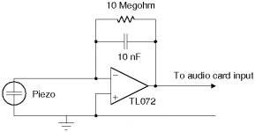
As seen in the previous diagram, you must have a proper piezo amplifier to get any kind of usable data. I quickly designed one for you, and here's the schematic.
I'm not sure what the capacitance of the piezo you are actually using is - so I designed this charge amplifier to work with any of them, even the 2nF one. It won't be the ideal design, but at least you can get some usable data with it.
The opamp must be JFET or MOSFET input; a good old TL072 (or rather, half of one!) is perfect for the job. I haven't shown power connections - you'll need the usual +/- 15 volts DC or so, and the usual filter and stability caps near the opamp power pins.
-Gnobuddy
Attachments
And the final piece of the puzzle: you need some sort of appropriate audio measurement software on that PC to do the sweep, and record the gain and phase data.
This is an area I know little about - I haven't tinkered with this sort of thing in decades, and haven't used any form of Windows at home since 2001. But Room EQ Wizard seems to have the capabilities you need, and it's free. Here is a relevant 'Web page:
Making Measurements
If anyone else on this thread knows of better (or alternative) software for making good audio transfer function measurements, please chime in with your suggestions!
-Gnobuddy
Let me recommend SpectraLab4.32. I'm using it since 2001.If anyone else on this thread knows of better (or alternative) software for making good audio transfer function measurements, please chime in with your suggestions!
This is a straight, simple & user-friendly 2-channel oscilloscope, 2-channel FFT-based audio analyzer, and audio generator.
It appears to remain downloadable from SpectraLab4.32
With SpectraLab4.32, you always know what you are measuring, and how.
For somebody knowing what's a 2-channel FFT analyzer, there is almost no learning curve, because the various modalities and menus reflect the textbook definitions of what a 2-channel FFT analyzer is supposed to do. This is a great advantage indeed. This explains the longevity of such remarkable software.
In case you don't know what's a 2-channel FFT analyzer, the best you can do is to learn what it is, before actually using it.
Everybody should realize that the only simple and true way for getting proper & non ambiguous gain and phase curves, is to rely on a 2-channel FFT analyzer, that's able to compare the input signal (left input as channel #1 input) against the output signal (right input as channel #2 input).
Therefore, you need a "Y" loop-back cable, sending the signal that's coming from the audio generator (left audio channel as output), a) to your circuit input, and b) back to channel #1 as input.
This, plus of course, a normal cable going from your circuit output, to channel #2 as input.
Let me be straight. Those ones not wanting to understanding this, should avoid doing electronics.
A Behringer UCA-202 stereo soundcard on USB is mandatory, as it is inexpensive, exhibits decent audio specs, and has four RCA (cinch) connectors. Two audio inputs (analyzer inputs), and two outputs (left output serving as signal generator).
Last edited:
I fully support you in this. Meanwhile, the piezo amplifier you are recommending is a "charge-amplifier". Put your finger on the piezo sensor, or on the 10 meg ohm feedback resistor, and you will see brutal parasitic waveforms, low frequency and high frequency, coming out from such kind of amplifier, potentially destructing the power amplifier and/or woofer.As seen in the previous diagram, you must have a proper piezo amplifier to get any kind of usable data.
I recommend a TL071 opamp (or half of a TL072 opamp) wired as DC-coupled voltage follower, plus a 2.2 meg Ohm resistor for providing some tiny DC path to ground to the opamp non-inverting input. Using such combination, whatever happens (finger on the piezo sensor or finger on the 2.2 meg resistor), the voltage amplification remains unity for all the frequencies. In case the piezo sensor exhibits a 20 nF capacitance, loading it by the 2.2 meg resistor causes a parasitic highpass filtering of the acceleration signal below 3.6 Hz. This is a pretty acceptable figure in the context of a loudspeaker aiming at reproducing 35 Hz at -3 dB. At 35 Hz, which is about 10 times the parasitic 3.6 Hz highpass corner frequency, the motional feedback signal phase "up" error remains insignificant. The only degradation you will see happens below 20 Hz, where the output of the system gets slightly higher with the MFB enabled, compared to the output of the system when the MFB disabled. In other words, below 20 Hz, the MFB will act as a tiny positive feedback, so tiny it doesn't impact stability. Nothing to worry indeed.
Your proposed "charge-amplifier" piezo preamplifier is more ambitious, as it parallels a 10 meg resistor on a 10 nF capacitor as local feedback. This also introduces a parasitic motional feedback signal phase "up" error. Albeit showing at 1.5 Hz. This is overkill for a system aiming at reproducing 35 Hz at -3 dB. Try limiting the devastating "finger ballad" consequences with a 20 nF feedback capacitor, and a 2.2 meg feedback resistor. In case the piezo sensor also exhibits a 20 nF capacitance, such "charge-amplifier" preamplifier will provide the same voltage output as the above described voltage follower preamplifier. Then comes the question of hum pickup, in case the shielding isn't perfect. Possibly the "charge-amplifier" piezo preamplifier exhibits less hum pickup, than the voltage follower piezo preamplifier. And possibly, by exploiting the piezo current instead of the piezo voltage, the "charge-amplifier" piezo preamplifier exhibits some improved linearity.
By the way, the "charge-amplifier" piezo preamplifier is of inverting nature. Please re-orient or re-wire the sensor polarity accordingly.
Last edited:
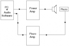
For the sake of completeness, your diagram needs to represent the two audio input along with the audio output, and also the loop-back cable that is required inside the "PC with audio software". Otherwise, you can't truly measure the phase.Now, here's a block diagram showing how you can get proper gain/phase sweep data.
Please note, a software like Arta pretends measuring a phase without needing a "reference" audio input, basing on the assumption that the measured system is of "phase-minimum" nature. What they do is to ONLY measure the freqency spectrum of the output signal, and from the hills and valleys of such frequency spectrum, they infer what could be the phase.
The phase against what?
This looks ridiculous.
I have three objections.
First objection is that most multiway speakers are not "phase-minimum" because of their crossovers inside. Okay, it can be that for assessing and measuring the working of a MFB woofer, that we stay inside the "phase-minimum" domain. However, the day you are going to assess and measure speakers crossovers, will you remember that the audio analyzer that you are accustomed with, dares to display a phase curve that's not truly measured?
Second objection is that a single channel FFT analyzer is less precise and immune to noise, than a dual-channel FFT analyzer. Using a dual-channel FFT analyzer, you'll be amazed to see clean curves showing up, requiring very little averaging compared to the averaging that's required using a single-channel FFT analyzer. This is because the dual-channel FFT analyzer duly compares the output signal against the input signal, in real time. While on the other hand, the single-channel FFT analyzer needs to build some statistical evidence, before the measurement actually stabilizes.
Third objection, is that single-channel FFT audio analyzers are no analyzers at all. They are just audio spectrum meters. They only output an audio spectrum curve. That you only can consider as a frequency response curve, at the condition that you feed the system with a high-quality white noise signal. Say you feed a system, using a high-quality white noise signal at the input of a system, labelled point A. Your single-channel FFT audio analyzer is unable to show the transfer function that's existing between some arbitrary point B and point C inside the schematic. This is because you can't guarantee that point B is still a white noise signal.
You may have noticed, a dual-channel FFT audio analyzer can operate, using a white noise signal, or a pink noise signal, or music, or any signal that has a rich and wide frequency spectrum.
Last edited:
Well, yes, but who would ever do that? Normally, you measure a system's transfer function with Farina-style log-sweep and convolution to obtain the impulse response (incl. distortion components) and then you do a complex FFT on this to get mag and phase vs frequency, and before starting you of course should normalize your rig in loopback or at whatever point you choose to be your reference (point B in your example).Say you feed a system, using a high-quality white noise signal at the input of a system, labelled point A. Your single-channel FFT audio analyzer is unable to show the transfer function that's existing between some arbitrary point B and point C inside the schematic. This is because you can't guarantee that point B is still a white noise signal.
I'm using HolmImpulse all the time and get 100% reliable and repetable mag and phase data.
Last edited:
As seen in the previous diagram, you must have a proper piezo amplifier to get any kind of usable data. I quickly designed one for you, and here's the schematic.
I'm not sure what the capacitance of the piezo you are actually using is - so I designed this charge amplifier to work with any of them, even the 2nF one. It won't be the ideal design, but at least you can get some usable data with it.
Thank you for all the great tips and clear schematics on how to proceed. Last week I downloaded REW but it wasnt obvious to me how to look at the phase difference of two signals but I will check it out again and study it more carefully.
The piezo I was using is 18nF, but I have several piezos with a range of capacitance up to 48 nF I could use.
You suggest one option is to bail on the MBF and just use the Sony as is - that is my back up plan - arranged as infinite baffle. Plus, I am in too deep now and too much $$$ (that I dont have!) in this side project to bail now - I have accumulated not one, not two, not four, but eight of these W2500's (I blame bentoronto for encouraging me to move on this idea - Ha 😀).
That frequency / amplitude sweep I showed above - I think there is all the info in there that is needed - the data just needs to be teased out and presented clearer - it has the simultaneous amplitude of the signal going into the Sony op amp mixer and relative amplitude and phase of the conditions signal output of the piezo. Hopefully some additional software like what you and Steph_tsf will help. I have also wondered if an iPhone app called AUDIOTOOLS will work - I have to check it out more carefully and see what additional "in app purchases' and hardware must be purchased to take phase readings.
Thanks!
I'll be up-front; I think there is zero chance that your piezo sensor will plug-n-play with the stock Sony electronics and actually produce any useful result. So you have come to a fork in the road: one road is to just bale on the whole DIY MFB idea, keep the woofer stock, and enjoy it as-is.
-Gnobuddy
Here is my back up to my back up MFB plan - based on the atomic force microscope (AFM). AFMs can measure the vertical and lateral deflections of the cantilever moving over a surface by using the optical lever. The optical lever operates by reflecting a laser beam off the cantilever. The reflected laser beam strikes a position-sensitive photo-detector. The differences between the segments of photo-detector of signals indicate the position of the laser spot on the detector and thus the angular deflections of the cantilever.

I figure these must be similar technologies now available for measuring larger movements / displacements etc. so I searched and found this. I figure if a person really got desperate, this could work very well for measuring woofer displacement / velocity / acceleration, and obviate some piezo problems...seems the specs are conducive to measuring woofer motion...Only about $1100 each. 🙁
Compact laser triangulation displacement sensor | Micro-Epsilon Measurement
They say "measuring rate 2 kHz", but what is the measurement delay (I guess this is digital electronics), and what is the measurement signal/noise ratio ?This could work very well for measuring woofer displacement / velocity / acceleration, and obviate some piezo problems...seems the specs are conducive to measuring woofer motion...Only about $1100 each. 🙁
Compact laser triangulation displacement sensor | Micro-Epsilon Measurement
Remember that an ideal MFB system requires a position (or velocity, or acceleration) sensor exhibiting a near-zero delay (otherwise the MFB loop will get unstable), a clean 600 Hz -3 dB bandwidth (otherwise the MFB will need to be reduced, so it doesn't involve frequencies at which the sensor gets blind), and a 60 dB signal/noise ratio (otherwise the woofer will continuously output some parasitic noise).
They say "measuring rate 2 kHz", but what is the measurement delay (I guess this is digital electronics), and what is the measurement signal/noise ratio ?
Good question I don't know what the delay is I was guessing insignificant. this laser also offers analog output. If one looks carefully at the brochure there is an example picture of a laser shooting at woofer.
When I first began thinking about building an MFB system, it had not yet occurred to me that the cone acceleration is the thing that is the closest match to the emitted SPL.Here is my back up to my back up MFB plan
Not having realized this, my very first attempt was to build a displacement (position) sensor. A few hours thinking and one dead-end approach later, I came up with one: an LED and photo-transistor facing each other and spaced a couple of millimetres apart, and an angled blade (like an Xacto knife, but not sharp) carried by the woofer dust cap, and positioned in between optical emitter and receiver.
With the speaker cone at its rest position, the blade blocked half of the light beam. If the speaker cone moved in, more of the light beam would be exposed; if the cone moved out, less of the light beam would be exposed. Presto, an optical signal proportional to cone displacement!
The angled "blade" is a key ingredient - varying the angle lets you tailor the speaker Xmax to the diameter of the LED's light beam, so that you get a relatively linear optical output over the entire range of movement of the speaker cone. The beam of light from, say, a 5mm LED is quite small in diameter, much less than the Xmax of a powerful modern woofer, so this approach is necessary.
So you don't need $1000 - with a little care, $10 should be plenty! 🙂
However, I abandoned this approach when I realized that a fifty-cent piezo disc was actually a much better sensor! 😀
-Gnobuddy
Yes, I know, I designed it! 🙂..the piezo amplifier you are recommending is a "charge-amplifier".
And if you beat it with a hammer, then the circuit will break and fall apart. 😱Put your finger on the piezo sensor, or on the 10 meg ohm feedback resistor, and you will see brutal parasitic waveforms,
The solution is quite simple, don't beat it with a hammer, and don't poke it with your finger, either! 😀
The reality is that a charge-mode amplifier like this has virtually zero input impedance, making it much less sensitive to noise, hum, and interference pick up. The high-Z approach you suggest, on the other hand, has severe problems in this area.
I speak from my personal experience - I tried both high-Z and charge-mode piezo preamps, and the charge-mode one gave me much better results.
In fact, the high-Z one would produce lots of hum and buzz if I merely moved my hand near the piezo. The charge-mode one was dead-quiet in the same circumstances.
If you happen to be using a piezo with rather high capacitance, the high-Z approach becomes more practical, as you don't need such an extremely high Z to make it work over the necessary bandwidth.
I know, I designed it! 🙂Your proposed "charge-amplifier" piezo preamplifier is more ambitious, as it parallels a 10 meg resistor on a 10 nF capacitor as local feedback.
I disagree. The aim is to get the woofer/piezo transfer response over the entire frequency range that needs to be considered for a servo design.Albeit showing at 1.5 Hz. This is overkill for a system aiming at reproducing 35 Hz at -3 dB.
Hombre's speaker currently seems to have its gain peak at 60 Hz; apply 20 dB of negative feedback, and the unity-gain frequency will be around 6 Hz.
Therefore the integrator in the charge-mode amplifier needs to continue to integrate down to well below 6 Hz. Which is why I chose the values I did!
Agreed, very much so, in my experience.Possibly the "charge-amplifier" piezo preamplifier exhibits less hum pickup, than the voltage follower piezo preamplifier.
I also found there was much less high-frequency interference too, due to the gain dropping with frequency at -6 dB/octave, and to the near-zero input impedance.
The acid test for linearity is to see if closed-loop distortion drops, compared to open-loop.And possibly, by exploiting the piezo current instead of the piezo voltage, the "charge-amplifier" piezo preamplifier exhibits some improved linearity.
With a 50-cent piezo, and a charge-mode preamp like the one I posted, I saw 15-18 dB of reduction in 3rd harmonic distortion at frequencies near the peak open-loop gain, with about 18 dB of negative feedback applied.
This is nearly the theoretical limit, so the distortion reduction was working very well indeed.
And that tells me that the piezo was, for sure, very much more linear than the woofer that I was using - which is what really matters!
For piezo discs of the sort I used, I found it best to keep the big brass disc grounded, for minimum hum and noise pickup. That fixes your piezo polarity once and for all.By the way, the "charge-amplifier" piezo preamplifier is of inverting nature. Please re-orient or re-wire the sensor polarity accordingly.
However, it is trivially easy to reverse the wires from the amp to the woofer! 🙂
None of this matters for the initial sweep measurements, though, since any overall phase reversal is pretty easy to take care of in the final servo design. I figured we'd worry about that when the time comes, if the time comes.
-Gnobuddy
That makes the charge-mode preamp a little less extreme, you can replace the 10 nF cap with a capacitor roughly the same size as your piezo capacitance. For example, 22nF with your 18 nF piezo, or 47 nF with your 48 nF piezo.The piezo I was using is 18nF, but I have several piezos with a range of capacitance up to 48 nF I could use.
If you do this, you can also reduce the 10M resistor proportionally. For example, if you replaced the 10 nF cap with a 47 nF one, you've just increased the capacitance five-fold, so you can decrease the 10M resistor by the same factor; 2.2M will be close enough.
I have a relative who, at one time in the late 1990's, bought dozens of those ridiculous Beanie Babies (stuffed toys), convinced they were her road to wealth and early retirement.I have accumulated not one, not two, not four, but eight of these W2500's (I blame bentoronto for encouraging me to move on this idea - Ha 😀).
It ended quite predictably ( The Beanie Baby Boom And Bust ? What Happened? | Here & Now ).
At least you have eight fully functioning woofers on your hands, rather than fifty-odd remarkably worthless stuffed toys! 😀
Has anyone told BenToronto that he is the designated scapegoat on this thread? 😀(I blame bentoronto for encouraging me to move on this idea - Ha) 😀.
Seriously, with eight powered subwoofers on your hands, you may be able to get all the bass you need or want by carefully distributing them around the room, and then using a little EQ to flatten the in-room response if necessary. You have so much woofer cone area, you should be able to get nice clean deep bass at pretty low frequencies without the woofers having to work hard.
-Gnobuddy
I can understand that after designing and debugging a MFB system using a plain genuine 2-channel analyzer (like SpectraLab4.32), comes the need to assess the harmonic distortion components (K2, K3, etc.), and there, I consider the 1-channel Farina method to be the most appropriated.Normally, you measure a system's transfer function with Farina-style log-sweep and convolution to obtain the impulse response (incl. distortion components) and then you do a complex FFT on this to get mag and phase vs frequency, and before starting you of course should normalize your rig in loop-back or at whatever point you choose to be your reference (point B in your example). I'm using HolmImpulse all the time and get 100% reliable and repeatable mag and phase data.
However, I think that the 1-channel Farina method (also available on Arta) is incapable of computing the actual phase curve.
Starting from there, we have two possibilities.
Possibility A : engaging a pseudo 2-channel modality when comes the time to graph a phase.
A pseudo 2-channel modality, consists of keeping track of the Farina test signal while still in digital domain, and applying a FFT on it so it can serve as reference, as comparison base. This is acceptable, provided the DAC (digital to analog converter) is perfect. The issue with this, is the quite long latency of the digital system consisting of the audio buffer inside the operating system, the audio buffer feeding the USB soundcard, and the DAC latency (FIR filter) inside the soundcard. Consequently, there is a huge delay mismatch between the digital-domain test signal copy, and the analog domain output signal, also needing to be channeled through the soundcard, the USB bus and the operating system. The already serious issue gets thus multiplied by two. And now comes the very bad news. Under Windows, you may have the audio subsystem taking decisions like spontaneously re-synching the audio buffer after one or another audio pause, for avoiding the risk of a buffer underrun or overflow. It follows that the delay may not be consistent. What a hell ! Consequently, you may not be allowed to proceed with averaging. Consequently, the pseudo 2-channel analyzer may be incapable of outputting a noise-free phase curve.
However, this is not the end of the world.
The first step is to compute a "draft" impulse response, even if we know if will be noisy, and time-misaligned. Such "draft" impulse response is equal to the inverse-FFT of ((FFT of output signal) / (FFT of digital copy of test signal)).
The clever software displays such impulse response to the user. Being misaligned, the pulse doesn't show at the time origin of the graph, but after some long delay, say 150 ms. The user scrolls for centering the 150 ms zone on the screen. The user then zooms on this, and he enters the "system delay" inside a dialog box. This way the time-misalignment can get compensated. And, if we are lucky enough during the whole measurement session, for the operating system not altering the audio buffer sizes, and not flushing them, we will be able to re-align the impulse response, and apply averaging on it. Basing on such "quality" impulse response that's building up, we compute the phase. The phase gets computed by doing the FFT of the "quality" impulse response. The frequency response curve gets also coputed this way. And, as a matter of verification, the frequency response obtained this way, should match the frequency response obtained through the Farina method.
Possibility B : engaging a "minimal-phase" estimator, basing on the frequency response hills and valleys obtained by the Farina method. What we get from such estimator, is not the actual phase, but some "minimal phase" supposed to match the actual phase in most cases. A + 6 dB/oct slope suggests a 1st-order highpass asymptotically reaching a "90 degree up" phase. A - 6 dB/oct slope suggests a 1st-order lowpass asymptotically reaching a "90 degree down" phase. In case the slope is + 12 dB/oct, the phase asymptotically reaches 180 degree. In case the slope is + 18 dB/oct, the phase asymptotically reaches 270 degree. And so on.
Such phase estimator can't make a difference between a buffer amplifier and an inverter amplifier (180 degree phase mismatch).
Such phase estimator outputs an erroneous phase curve when confronted to a multiway speaker that's embedding a Linkwitz-Riley crossover, because such crossover that's guaranteeing the phase synchronicity of the drivers, is never "phase-minimum".
The 2nd-order lowpass filter that's required for the woofer, exhibits some significant phase lag around the the crossover frequency, while at the same time the 2nd-order highpass filter that's required for the tweeter, exhibits some significant phase advance around the crossover frequency.
How can thus a Linkwitz-Riley crossover guarantee the two phases synchronicity. What's the trick ?
First part of the answer is to hook the tweeter in phase reverse (180 degree phase shift). This way, you just created a system that's not anymore "phase minimal". The woofer exhibits a 90 degree phase lag at the crossover frequency. The tweeter that's mounted with reverse phase, exhibits a 90 phase advance (filter) plus 180 phase shift (reverse) = 90 degree phase lag at the crossover frequency. Phase synchronicity is thus guaranteed. The filtered tweeter phase copies the filtered woofer phase. The global phase copies the phase of the filtered woofer phase. Sound weird, isn't ? Such is a non "phase minimal" system. It exhibits a straight global frequency response curve (sum of woofer and tweeter), albeit exhibiting a global phase that's identical to a 2nd-order lowpass system.
Second part of the answer (about properly designing a 2nd-order Linkwitz-Riley crossover) is to ensure that there is hill or valley in the global frequency response (woofer + tweeter acting together). This is easy achievable, by selecting a 2nd-order Q factor equal to 0.500, same for the highpass and the highpass, also designed for exhibiting the same same -6 dB point frequency.
Do you see the difference between :
- a genuine 2-channel analyzer that's immune to the above situations,
- a pseudo 2-channel modality working on a digital copy of the test signal,
- a minimal phase estimator, basing on the frequency response hills and valleys obtained by the Farina method.
Considering what's above, for me there is no other choice than designing and debugging a MFB system using a plain genuine 2-channel analyzer like SpectraLab4.32.
Or possibly, I'm wrong and outdated, ignoring some major feature of the Farina method disclosed at the 108th AES Convention, Paris, 2000.
Hmmm, 8 non-MF woofers may be a good concept* but hardly advances the state of the art, eh.Seriously, with eight powered subwoofers on your hands, you may be able to get all the bass you need or want by carefully distributing them around the room, and then using a little EQ to flatten the in-room response if necessary. You have so much woofer cone area, you should be able to get nice clean deep bass at pretty low frequencies without the woofers having to work hard.
Which brings up another MF debate: can you sense the behaviour of a single driver and use it to correct a bunch of similar drivers?
Doing so violates my feedback aesthetics because the cohort would have to be as perfectly matched (and matched in distortion and errors) as finely as the feedback system is designed to attenuate. But there are manufacturer(s) that do it.
Once again, a matter of goals. If you just want to rein-in the main resonance (shared by all the drivers) and pump-up the bottom end, you can do it.
Ben
*while 8 subs haphazardly arrayed around your room may be stochastically smart, 8 drivers of different sorts is better stochastically.
Last edited:
Now you've gone and done it, Ben. Next time we hear from Hombre, he'll have 64 woofers of 8 different brands! 😀...8 drivers of different sorts is better...
-Gnobuddy
I found other sources - digikey & mouser for piezos. Any suggestions on what properties I should select - light weight, ~20mm diameter, highest capacitance, high or low frequency resonance?
Something like this?
AB2025B PUI Audio, Inc. | Audio Products | DigiKey
Something like this?
AB2025B PUI Audio, Inc. | Audio Products | DigiKey
- Home
- Loudspeakers
- Subwoofers
- Commercial motional feedback woofer available sort of