I found other sources - digikey & mouser for piezos. Any suggestions on what properties I should select...
Distortion. Why is this key parameter getting lost sight of?
(64 woofers sounds grand, but the marginal increases in performance from averaging become pretty marginal once you get past four.)
B.
Hi,
@#635
In the mid-80s T+A introduced their Solitaire OEC speaker line with motional feedback woofers.
They utilized a optical displacement sensor made from a LED, a light sensor (probabely a photo transistor) and a conical shade between them.
The sensor assemly was mounted to the backside of the magnet and the shade was attached to the dustcap, protruding through the hollow pole piece.
See a pic in this link.
They got a patent granted under DE3426231
jauu
Calvin
I grabbed one out of the junk-box, and it worked just fine.Any suggestions on what properties I should select - light weight, ~20mm diameter, highest capacitance, high or low frequency resonance?
AB2025B PUI Audio, Inc. | Audio Products | DigiKey
If you have a choice, higher capacitance makes things a bit simpler, light weight is definitely good, and high self-resonance frequency is definitely good. You want the self-resonance frequency of the piezo well above the frequency of the first speaker cone break-up mode, at a minimum.
-Gnobuddy
There have been several references to piezo distortion on this thread. Is there any experimental evidence that this is, in fact, an issue? If so, do we know why there was piezo distortion in those cases?Distortion. Why is this key parameter getting lost sight of?
I know for a fact that piezo distortion was not a factor in the one and only MFB system I designed and built. The fact that closed loop distortion fell by nearly the same factor as loop gain, when negative feedback was applied, tells me the feedback was working just about perfectly; ergo, the piezo was producing a nearly perfect feedback signal.
As I mentioned previously, I supported the piezo all around it's circumference, and did not add any additional mass to it. The piezo was therefore very stiff, with a self resonant frequency of several kHz (I think it was up around 5 kHz, but am not sure after all these years). A stiff piezo will deflect very little, which is going to have the side effect that it will also be very linear.
There is another way of looking at this: woofers are quite horribly non-linear. When I measured one, I was quite shocked to find that it wasn't hard to get 20% third harmonic distortion out of one, if you drove it near or below its resonance frequency, a regime where the extremely non-linear spider and surround control cone motion.
That absurdly high woofer distortion, in turn, means that as long as the piezo produces much less than 20% THD, it will improve the performance of an MFB woofer. Not a very high standard to beat!
The other thought that crossed my mind when I saw that 20% THD number was the utter absurdity of developing audio amplifiers with 0.0005% THD, only to connect them to speakers with 20% THD - that's twenty thousand times more distortion from the speaker than the amp!
Peter Walker of QUAD fame said many decades ago that amplifiers were already very good, and the biggest limiting factor was the loudspeakers and the room they were in. Since that time, we've got rid of many other smaller limitations - with the arrival of CD-quality digital audio, we disposed of tape hiss, tape saturation, tape print-through, wow, flutter, rumble, record surface noise, inaccurate RIAA equalization, pickup cartridge resonances, record groove print-through, et cetera, et cetera.
But the one thing we never really made much progress with was loudspeakers, and room interaction; the biggest problem of all!
Does anyone else feel as though we've been ignoring the elephant in the room for decades now? So long, that we've even forgotten it's there at all, standing in the corner, swinging its trunk menacingly and glaring at us?
-Gnobuddy
I guess I re-invented their sensor, then, except my version used a two-dimensional beam-blocking shutter, rather than a conical one.They utilized a optical displacement sensor made from a LED, a light sensor (probabely a photo transistor) and a conical shade between them.
That looks like a structurally weak mounting method, meaning the "shutter" would probably wobble and vibrate rather easily. If it did, it would corrupt the feedback signal in the process....the shade was attached to the dustcap, protruding through the hollow pole piece.
Good thing it never crossed my mind to try and get a patent on my own version of this idea, then! (Though people like Edison specialized in tweaking someone else's idea just enough to make it legally possible to patent it as his own.)They got a patent granted under DE3426231
-Gnobuddy
Many thanks to Calvin for posting the photo sensor and to Gnobuddy for clarifications on the distortion of crystals and the photo sensor. But some of the wobbling of the photo sensor Gnobuddy describes are not artefacts but are "legitimate" errors that legitimately need reduction.That looks like a structurally weak mounting method, meaning the "shutter" would probably wobble and vibrate rather easily. If it did, it would corrupt the feedback signal in the process.
The photo sensor is interesting in that it is in a class of sensors that are truly DIY, also capacitative or heat-sensing (kidding about that one). You could mount it in front of the dust cap too. In that case, unlike bulking up and gluing an accelerometer to make it structurally stable, the detector mechanism can be as brawny as you like since it isn't part of the moving system. And you can more easily play with it, being in your face.
BTW, the photo sensor is a position detector, good down to DC!
But here's the (same old) problem: let's say you are holding your scissors or X-Acto knife and cutting the mask; to reduce distortion below say 1% you need to cut that mask (and the whole rest of the sensor system) to a very high degree of accuracy.
Ben
Last edited:
I was thinking about lateral wobble - side to side rocking modes of that long spear of a sensor....some of the wobbling of the photo sensor Gnobuddy describes are not artefacts but are "legitimate" errors that legitimately need reduction.
Because the light-beam isn't uniform across its cross section, lateral movement of the "shutter" will cause changes in the photo-detected signal, and this doesn't represent cone motion at all, just dust-cap and "shutter" flexibility.
When you spoke of legitimate errors, I'm guessing you were thinking of various rocking or wobbling modes of the speaker cone itself. Those errors might be legitimate, but a one-axis MFB system is not going to be able to correct them, in any case.
I suspect these (cone wobble) errors are quite small, though, since otherwise the voice coil would touch the magnet and pole piece assembly, and be damaged very quickly.
The other thing that occurs to me is that if the speaker cone did wobble side-to-side, the emitted sound from one half of the cone would (to first order) cancel the emitted sound from the other half of the cone; in other words, small rocking movements should have much less effect on the emitted sound, compared to small errors in axial movement. A good thing, too, since MFB can only correct for axial cone movement!
Agreed, and I actually did use an Exacto knife blade as an optical "shutter" in my early experiments, for exactly this reason. It was precision-ground by modern machinery, surely to a higher tolerance than anything I could make by hand with limited resources.to reduce distortion below say 1% you need to cut that mask (and the whole rest of the sensor system) to a very high degree of accuracy.
It looks like the patent Calvin referred to included a shutter profile that was not straight, but curved, presumably to make the overall sensor more linear by correcting for some higher-order terms.
There are distinct downsides to the optical system, though. For one, it senses the wrong thing, since sound emitted by the speaker is proportional to cone acceleration, not position. For another, it is easily disturbed by light pollution - fluorescent lights, for instance, are a major headache. The DC bandwidth is not as much of a good thing as it appears at first sight, either - for example, bright sunlight will completely overpower the faint LED illumination, saturate the optical sensor and/or its electronics, and throw the entire sensor out of whack. That's probably why the commercial implementation was designed to live behind the woofer, in the dark insides of a speaker cabinet.
In the end, I'm pretty convinced that an accelerometer is the best type of sensor. I keep thinking there must be a nice 100-G MEMS sensor out there. But if there isn't, a quite unglamorous fifty-cent piezo ceramic disc from a Hallmark musical greeting card seems to do a quite excellent job!
And then there is the unexplored "mic in front of the speaker" idea - completely non-contact, so very easy to engineer. At 1 kHz, it takes roughly a foot of air to accumulate 360 degrees of (acoustic) phase shift due to the finite speed of sound; if the mic was within an inch of the speaker cone, then, additional phase shift would be in the region of 30 degrees, and even less at lower frequencies.
That small phase-shift is very reasonable, and it should be entirely possible to engineer a servo feedback system around it.
Too bad electret mics are a dying breed now. Apple Corp switched to MEMS microphones because they were smaller (and, very likely, cheaper), and that seems to have dealt a death-blow to the electret mic industry. The really good, cheap, (flat down to 20 Hz and below) electrets seem to have gone off the market now. The few MEMS microphones I could find data for, are not as good as the best of those old electret mics.
Then again, nobody else seems to have any interest in the "mic for MFB feedback" concept, so perhaps it doesn't matter! 🙂
-Gnobuddy
@ hombre,
Appologies for tardy reply…will likely be after the new year before I will have time to keep up with activity here.
GRS PZ1016 2" x 5" Piezo Horn Tweeter Similar to KSN1016A
Although not mandatory at this point, it would be best to include the piezo buffer circuit you intend to use as part of the measurement.
Also, remember you need to acquire magnitude and phase data from 10Hz up to at least 5kHz.
Appologies for tardy reply…will likely be after the new year before I will have time to keep up with activity here.
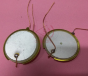
Not sure if you caught the logic, but my comment was based on the 440K input impedance. If their piezo didn’t have higher capacitance it would be adding significant phase lead below 30Hz making LF stability an issue. The higher capacitance, and louder sound you mentioned all seem to point to the Genesis piezo as being a bimorph, or dual layer piezo as is commonly used for piezo tweeters. You can see the jumper connection between the front and back piezo clearly in the attached front/back piezo pics. Once you know what to look for, you can see it in the Genesis pic you posted. If interested, see piezo tweeter element pic here:5. Genesis measured but not seen, louder sound than all the others when measuring - 77nF….Bolserst, I am duly impressed with your prediction of the Genesis piezo capacitance being much higher than the one I was using (18nf)
GRS PZ1016 2" x 5" Piezo Horn Tweeter Similar to KSN1016A
Basically you do as KSTR mentioned and calibrate with a loopback test. This sets the reference response flat and reference phase to zero for the signal you are injecting into the circuit. Any measurement you make from then on will show magnitude and phase changes relative to that reference.Thank you for all the great tips and clear schematics on how to proceed. Last week I downloaded REW but it wasnt obvious to me how to look at the phase difference of two signals but I will check it out again and study it more carefully.
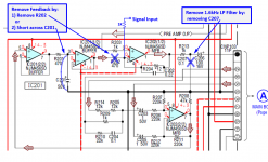
You are getting closer to measurement of the open loop response, but not quite there. Gnobuddy provided some nice clear diagrams of how to proceed. If you intend to stick with the Sony electronics, you will need to 1) inject your known flat response at the mixer, 2) disconnect or remove the feedback path from the OEM circuit, 3) remove the 1.6kHz LP filter after the mixer. See attached circuit for details.I think there is all the info in there that is needed - the data just needs to be teased out and presented clearer - it has the simultaneous amplitude of the signal going into the Sony op amp mixer and relative amplitude and phase of the conditions signal output of the piezo.
Although not mandatory at this point, it would be best to include the piezo buffer circuit you intend to use as part of the measurement.
Also, remember you need to acquire magnitude and phase data from 10Hz up to at least 5kHz.
Attachments
Thank you very much for providing this information and download link!Let me recommend SpectraLab4.32. I'm using it since 2001.
This is a straight, simple & user-friendly 2-channel oscilloscope, 2-channel FFT-based audio analyzer, and audio generator.
It appears to remain downloadable from SpectraLab4.32
Sorry it took me so long, I thought I had already thanked you for this, but when I re-read the thread, I realized I hadn't.
One of these days I might have to get some old PC hardware, and let the hard drive get infected with the monster that Bill Gates used to sell, just so that I can use some of these software tools that are out there.
-Gnobuddy
Let's say the Genesis bimorph piezo capacitance is 42 nF. Knowing it gets loaded by a 440 k resistance (see U3A arrangement as balanced amplifier), this determines a highpass filter at approx 8.5 Hz.Not sure if you caught the logic, but my comment was based on the 440K input impedance. If their (Genesis) piezo didn’t have higher capacitance it would be adding significant phase lead below 30Hz making LF stability an issue. The higher capacitance, and louder sound you mentioned all seem to point to the Genesis piezo as being a bimorph, or dual layer piezo as is commonly used for piezo tweeters.
A MFB signal equalizer (bass boost) is thus required, in the form of U3D that's acting as progressive bass booster (integrator) below 8.5 Hz, and voltage follower (0 dB gain) above 8.5 Hz. The integrator time constant is defined by C9 (470 nF) and R42 (39 k), equal to 18 ms roughly. The U3D integrator provides thus a 3 dB boost at the frequency (8.5 Hz roughly) where C8 reactance module equals R42 resistance.
Such progressive amplification increase below 8.5 Hz truly compensates the piezo loading 8.5 Hz highpass filter.
Problem with "true" integrators, is that they exhibit an infinite gain at 0 Hz (DC).
For overcoming this, the U3D feedback network features R41 (220 k) as extra-resistor, transforming U3D into a "leaking" integrator, determining a quasi-DC frequency below which the amplification doesn't rise anymore.
Considering R41 (220 k) and R42 (39 k), the amplification coefficient for the DC is approx 7. The DC gain is thus approx 16 dB, to be considered as limit for avoiding U3D opamp output coming close to the supply rails, in case there is subsonic content in the audio signal. Think about playing a vinyl disc using a DC-coupled RIAA preamp and a DC-coupled control preamplifier. This is not a joke, as the targeted audience for Genesis systems are audiophile people paying a lot of money for everything that's relating to audio, including vinyl discs, RIAA preamps and control preamplifiers.
Considering C9 (470 nF) and R41 (220 k), the U3D "leaking" integrator stops working as integrator below the frequency (1.5 Hz roughly) at which C9 reactance module equals R42 resistance.
Below 1.5 Hz, the system cannot base on the MFB signal anymore, that's exhibiting some considerable phase "up" that would ruin the loop stability. The phase "up" is 45 degree at 1.5 Hz. The phase "up" is 90 degree for DC.
For guaranteeing the stability of the system at DC and in the subsonic frequencies, a rule of thumb is to ensure that at 4 times the MFB signal low frequency limit (4 times 1.5 Hz equals 6 Hz), half of the feedback comes from the power amplifier voltage output, and half of the feedback comes from the MFB signal.
DC to 3 Hz : the power amp output voltage feedback is dominant.
6 Hz : the MFB coexists at 50% with the power amp output voltage feedback.
12 Hz to 300 Hz : the MFB is dominant.
600 Hz : the MFB coexists at 50% with the power amp output voltage feedback
1200 Hz and above : the power amp output voltage feedback is dominant.
Most MFB system base on conventional power amplifiers exhibiting a flat gain from 3 Hz to 300 kHz. It gets difficult for the MFB to become truly dominant from 12 Hz to 300 Hz, as the power amplifier embeds a parasitic "always on" voltage feedback, always interfering with the MFB.
A quick fix consists of placing an equalizer/amplifier/mixer inside the feedback loop, just before the conventional power amplifier.
The Genesis does so thanks to U4B. The aim of U4B is to provide the x10 open-loop amplification supplement that the MFB is requiring (R50, R51), along with some progressive extra-gain in the deep bass below 72 Hz (C15, R51) till 32 Hz (C15, R55) where the amplification coefficient reaches a value of x32 for the DC.
Knowing that amplifying the DC by such coefficient can be dangerous, Genesis decided to introduce a large coupling capacitor (C11) attenuating the frequencies below 0.16 Hz (R50). Unfortunately, this introduces another parasitic highpass in the chain (we don't deal with the potential issue here).
Anyway, the 32 Hz to 72 Hz equalization tries to impose more MFB from 32 Hz to 72 Hz in order to somewhat improve the MFB dominance at such frequencies.
Please note C14 (33 nF) determining with R51 (100 k) a lowpass filter in the action chain, gradually attenuating the frequencies past 482 Hz. Clearly, the x10 open-loop amplification supplement that's required by the MFB, only holds till 482 Hz. Consequently, the extra open-loop amplification completely vanishes at approx 4.8 kHz, reaching unity at such frequency. That's plain normal, as probably, the MFB sensor starts exhibiting some irregular gain and phase above 2 kHz, potentially caused by himself, or caused by the way it gets fixed on the speaker cone.
In case the aim is to build a MFB woofer in the context of a 2-way speaker, the woofer is required to produce a flat frequency spectrum till 3.4 kHz or so, before applying some (possibly active) woofer crossover. The Genesis schematic may be suited to this.
In case the aim is to build a MFB system in the context of a fullrange speaker, the fullrange speaker is required to produce a flat frequency spectrum till 15 kHz or so. The Genesis schematic is not suited to this, as beyond 4.8 kHz the action chain signal remains filtered following a -6 dB / octave slope. For overcoming this, a 10 k series resistor should be installed with C14. Possibly this will ruin stability. Or not.
By looking to C12 (22 nF) and R47 (100 k), we realize that Genesis implements a lowpass filter at the input, outside of the feedback loop. Such lowpass filter is gradually attenuating the frequencies past 72 Hz. One possibly could reduce C12 value for increasing such high frequency limit.
For reaching 120 Hz, 12 nF are required.
For reaching 300 Hz, 4.7 nF are required.
For reaching 1.6 kHz, 1 nF are required.
In a previous post, I showed how to properly implement a MFB that's "really dominant" from 12 Hz to 300 Hz.
Attachments
Last edited:
@ hombre,
You are getting closer to measurement of the open loop response, but not quite there. Gnobuddy provided some nice clear diagrams of how to proceed. If you intend to stick with the Sony electronics, you will need to 1) inject your known flat response at the mixer, 2) disconnect or remove the feedback path from the OEM circuit, 3) remove the 1.6kHz LP filter after the mixer. See attached circuit for details.
Although not mandatory at this point, it would be best to include the piezo buffer circuit you intend to use as part of the measurement.
Also, remember you need to acquire magnitude and phase data from 10Hz up to at least 5kHz.
Thank you for the guidance and link to the other piezos.
I was originally thinking to use the sony filters in situ so I would only have to concern myself with the piezo behavior in the ~ 20-200Hz range and not much output above that as filtered in preamp before getting to the mixer. So I was going to focus my efforts on trying to get the amplitude and phase match - at least within +/- 179 degress from the piezo output to the input right before the mixer - seems do-able?
Please see next post below - I tried something, probably a lateral move but helped my understanding of what is going on.
Let's say the Genesis bimorph piezo capacitance is 42 nF. Knowing it gets loaded by a 440 k resistance (see U3A arrangement as balanced amplifier), this determines a highpass filter at approx 8.5 Hz.
Thank you for the in depth explanation! Could I ask you to elaborate on what U3A is doing? I look at this U3A circuit as a buffer / differential amplifier with a gain of -1? - so if the piezo sine wave output is say +/- 1V AC, the output from U3A should also be +/- 1V AC? But, isnt the positive leg of the piezo being simultaneously cancelled by the negative leg going into this op amp? The reason I ask , I thought I emulated this op amp circuit but am getting great attenuation - either I have the piezo hooked up wrong / [not sure I understand the 4 pin jumper as only two wires coming out of the piezo] or I messed up this simple op amp circuit - any further clarification greatly appreciated.
Next - I have the remnants of a blown Genesis amp, but I figured, the preamp circuit is probably okay. {This timing of this post is fortuitous with Steph_tsf's above post}. Anyhow, I dont know how I did it, but I somehow rigged it / got +/- 12V power to it (the preamp of Genesis) up so I can run the Sony piezo output through the Genesis MFB circuit (BLUE trace) and compare it to the signal going into the Sony mixer op amp (from IC104 1/2) (noisy YELLOW trace). Please see attached pic. I note a strong signal from the piezo after being conditioned by the Genesis preamp (not being attenuated like my lame circuit); I also note the phase shift problem still evident. Basically, this is looking at the circuit I would like to make (already made by Genesis and being tested here) that I would like to superimpose in the Sony MFB circuit - which to me looks like they share a lot of similarities. Side note - the conditioned output from the piezo looks better than the input signal - Lol!

Unfortunately, that's not true. If the MFB servo loop is oscillating wildly at 2 kHz, it doesn't matter whether the music is being low-pass filtered at 200 Hz or not! 😀...so I would only have to concern myself with the piezo behavior in the ~ 20-200Hz range and not much output above that as filtered in preamp before getting to the mixer.
I'll repeat again, to ensure that the servo is stable, it is necessary to have the piezo/woofer transfer function (amplitude and phase) from around 10 Hz to around 5 kHz.
This has nothing whatsoever to do with various things you've mentioned - testing at low volume, lowpass filtering of the incoming audio signal, et cetera. None of those things has any helpful effect on servo loop stability.
It might help to remember that a system with a feedback loop generates its own input - the feedback signal itself. If things go wrong with the feedback, it will take off and howl (oscillate) due to the feedback signal itself acting as input. It doesn't matter what or whether any other audio signal is also being fed into the amp - it will howl, regardless.
The only way to keep it from howling is to know in advance what that feedback signal is going to look like, and design the servo in such a way that it remains stable with that known (feedback) signal.
In other words, you need the speaker/piezo transfer function, both gain and phase. And you need it over the entire range of frequencies where the servo amplifier might oscillate - not the range of frequencies you ultimately hope to feed into the subwoofer.
Without this speaker/piezo transfer function measurement, everything is just a blind shot in the dark. Running blind like that, I can throw together a simple design incorporating an integrator in the forward path, a charge-mode piezo preamp with switchable phase inversion, a mixer stage, and a pot that lets you dial in the amount of negative feedback.
You could then hook it up to your speaker and piezo, and it will almost certainly work, after a fashion. But it will provide very little MFB action, and will definitely take off and howl if you turn up the feedback too far. And that could be a quite unpleasant (and potentially expensive) experience.
If you intend to proceed with the project, there is really no good way around needing that 10 Hz - 5 kHz gain and phase sweep!
It doesn't have to be hard. The only part you have to build is the piezo preamp, and the schematic I gave you is quite a simple one, you could build it in a few minutes on a breadboard.
Other than that, if you have an old PC running Windows available, it's a matter of downloading some free software (REW or the one Stephen suggested), spending some time learning how to use it, and running a few sweeps, after you connect it up to a power amp, your woofer, and your new piezo preamp.
There are additional luxuries that would be nice to have (like the two-channel audio interface Stephen mentions), but they are luxuries, not necessities. A loop-back measurement and sweep taken with the stock audio card in your PC will do just fine, for a simple home-brew design like this.
-Gnobuddy
Agree 100%. Gnobuddy is right. Meanwhile, our friend hombre has not yet reported about instability, howling or oscillation. This is bizarre. Possibly hombre piezo MFB schematic is still defective.If the MFB servo loop is oscillating wildly at 2 kHz, it doesn't matter whether the music is being low-pass filtered at 200 Hz or not! I'll repeat again, to ensure that the servo is stable, it is necessary to have the piezo/woofer transfer function (amplitude and phase) from around 10 Hz to around 5 kHz.
Like Gnobuddy wrote, our friend hombre should build a piezo preamplifier breadboard featuring a proper low frequency compensation, featuring a selectable MFB phase reversal, featuring a lowpass filter defining the high frequency where the MFB gradually vanishes at F1 (say 1 kHz ?), and featuring a potentiometer allowing to vary the MFB signal amplitude, prior entering the mixer.
Like Gnobuddy wrote, our friend hombre should also build a mixer breadboard featuring the mixer (MFB signal merging with the audio input signal), featuring the loop amplifier (say a x10 wideband amplification), featuring some extra bass boost (say a x3 amplification at 30 Hz), and last but not least, featuring the required lowpass shelving filter that's in charge of resetting the loop amplification to x1 at F2 (say 1 kHz also ?) and all the above frequencies. The last bit being critical what's regarding stability.
Only in case the MFB application is a subwoofer, the above lowpass shelving filter can become a leaking integrator that's resetting the loop amplification to x1 at F2 (say 1 kHz also ?), and because of its integrating nature, that's also imposing a 6 dB attenuation at 2 kHz, 12 dB attenuation at 4 kHz, 18 dB attenuation at 8 kHz, 24 dB attenuation at 16 kHz, and so on. Progressively muting the high frequencies above F2 inside the action chain, improves the MFB stability margin.
Last edited:
+1 for both previous cautionary posts.
With TWO such uncooperative devices in the loop (dime-store piezo crystal and Rice-Kellogg 1925 driver) hard to make MF fly except by working in a narrow frequency band delimited by roll-offs in the electronics.
Working with the Sony circuit board is forever going to be a patch-up job. Starting with a clean breadboard and modest bandwidth aspirations makes more R&D sense.
Historically, MF has been for subs and only subs and even for that narrow bandwidth has been hard for legitimate manufacturers to commercialize and warrantee (but fruitful for DIYers).
Ben
bolserst -...As I have said several times in this thread and the other MFB threads, VC feedback can reduce distortion at the low end of the frequency range by(2x – 3x)where the compliance distortion is greater than the magnetic distortion. Up at 40Hz to 80Hz, VC feedback provided no benefit in distortion reduction…often even increasing the distortion a bit. It does provide the response flattening desired though.
I've been reading the R. Valk masters thesis. When using an accelerometer associated with the voice coil region, he demonstrates that a lot of uncorrected distortion remaining (which isn't very big anyway) arises from parts of the cone distant from the VC. Choice of driver therefore has a lot to do with how much distortion is reduced and at what frequencies.*
So I am wondering about your tests which you say did not demonstrate desired reductions in distortion.
Choice of driver?
Ben
*I've always been more concerned with transient behaviour, Q, and "group delay" and that is adequately addressed by sensing at the driver core.
I think you are talking about the first woofer choice which was a small 6.5” woofer with unusually large surround. Looking at Section 3.2 you can see that the first cone break up mode was around 600hz, so not a factor The issue was that the radiating area of the surround was nearly as large as that of the cone. Since the surround is flexible, it can’t be directly controlled by the VC motion. The second woofer choice used in the later part of the thesis was a 10” woofer with more traditional ratio of cone to surround area.When using an accelerometer associated with the voice coil region, he demonstrates that a lot of uncorrected distortion remaining (which isn't very big anyway) arises from parts of the cone distant from the VC. Choice of driver therefore has a lot to do with how much distortion is reduced and at what frequencies.*
In each case, when comparing VC vs. acceleration based feedback the same woofer was used. The accelerometer was mounted to the VC. When measuring with a microphone, the VC based feedback did not provide the level of distortion reduction that the accelerometer did with the same level of feedback. And, as previously mentioned, above 40Hz the VC based MFB system often actually increased distortion while the accelerometer based system continued to reduce distortion by the factor theory predicted.So I am wondering about your tests which you say did not demonstrate desired reductions in distortion. Choice of driver?
These 3 items are directly tied to the frequency response, in other words they are a function of linear distortion not non-linear distortion. So, if these are your main concern, you can adjust them to your liking by simply applying appropriate EQ. MFB can also get you there, but it is a lot more complicated.*I've always been more concerned with transient behaviour, Q, and "group delay" and that is adequately addressed by sensing at the driver core.
*******
Valk Thesis Paper: http://wouterjan.deds.nl/MFB_Thesis.pdf
Many thanks for your as-always helpful replies.These 3 items are directly tied to the frequency response, in other words they are a function of linear distortion not non-linear distortion. So, if these are your main concern, you can adjust them to your liking by simply applying appropriate EQ. MFB can also get you there, but it is a lot more complicated.
But about making subs sound great just with EQ, that would be a wonderful world to live in.
B.
The three items you mentioned that can be manipulated with EQ are measureable properties of the sub as an acoustic source. Put that source into a room and the resulting sound may or may not be to your liking(ie sound great). Depending on the room dimensions, construction materials, and your flexibility in source and listener positioning, you might not be able to make even an ideal LF source sound great....about making subs sound great just with EQ, that would be a wonderful world to live in.
My education is incomplete because I don't understand how you can use just EQ to do much to correct the "three" features of electro-dynamic speakers which MF certainly can address.The three items you mentioned that can be manipulated with EQ are measureable properties of the sub as an acoustic source...
Brought up earlier, these are: transient behaviour, Q, and "group delay"
You earlier posted, "These 3 items are directly tied to the frequency response, in other words they are a function of linear distortion not non-linear distortion. So, if these are your main concern, you can adjust them to your liking by simply applying appropriate EQ."
Ben... Toronto again
- Home
- Loudspeakers
- Subwoofers
- Commercial motional feedback woofer available sort of