I worry that the larger choke has exactly the same DCR as I already have and is so physically large that it will pick up radiated noise from the traffo. Active rectifiers and cheapo-modo designed snubbers are already providing quite smooth rails.
Don't want to take a £75 gamble (in the UK) to find out if there's an improvement
Don't want to take a £75 gamble (in the UK) to find out if there's an improvement
Last edited:

I have CLC filters in my amplifiers. The main reason is for the lower ripple as I have 103dB sensitive speakers, and the ripple in CRC filtered supplies were audible. With the CLC filter, I hear no noise.
If your CRC filtered amplifiers are quiet with your speakers, then save your money. 🙂
If your CRC filtered amplifiers are quiet with your speakers, then save your money. 🙂
@Dan K
I bought a pair of these (Monacor 5.6mH 0.3R) for crossover testing. Maybe you could try them in your potential CRC?
https://www.ebay.co.uk/itm/22212487...aV1Cg3-Rh-&var=&widget_ver=artemis&media=COPY
I bought a pair of these (Monacor 5.6mH 0.3R) for crossover testing. Maybe you could try them in your potential CRC?
https://www.ebay.co.uk/itm/22212487...aV1Cg3-Rh-&var=&widget_ver=artemis&media=COPY
Ah I had wondered about that. Thanks.
Monacor do some laminate core jobs for XO work which may be more suitable, available in the UK and not daft expensive.
Monacor do some laminate core jobs for XO work which may be more suitable, available in the UK and not daft expensive.
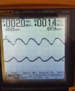
I've just measured my PSU +ve/ - ve rail ripple voltage, whist the amp was playing
Approx 2mV!
Not bad at all, it varies from as low as 1.4mV up to 2.6mV, but that could well be due in part to my melted scope probes.. Not the best that I've ever achieved, but certainly very decent
Approx 2mV!
Not bad at all, it varies from as low as 1.4mV up to 2.6mV, but that could well be due in part to my melted scope probes.. Not the best that I've ever achieved, but certainly very decent
Attachments
CLC is always better, tecnically and sound-wise
now, cost in space and money, calc is on builder itself
now, cost in space and money, calc is on builder itself
I've just measured my PSU +ve/ - ve rail ripple voltage, whist the amp was playing
Approx 2mV!
Are you sure your probes are not set at 10:1 ratio while scopemeter is set at 1:1?
2.6 mV pp ripple is not possible with 22 mF capacitors and 3 A load. Calculations predict minimum of 30 - 50 mV rms ripple at the second capacitor. Practice confirms that too.
I have never seen such low noise figures with CRC. On my noisy BA-3 PSU ripple was 130mV. Now it is zero, but with 10mH chokes, dual mono supply, and approx 800.000uF capacitance.
Doubling up caps will approx give half «spec ripple». So if std is 40-50, 20 is perhaps more likely than 2. excited to see the results!!
I have been trying to get my arms around PSU measurements for some time. While I don't completely grasp it, I think I've got a reasonable understanding. I've used the video linked as a primary reference / something to mimic.Are you sure your probes are not set at 10:1 ratio while scopemeter is set at 1:1?
2.6 mV pp ripple is not possible with 22 mF capacitors and 3 A load. Calculations predict minimum of 30 - 50 mV rms ripple at the second capacitor. Practice confirms that too.
There are a few other things that could contribute. I know that you know that I know that you know your way around a scope and measurement technique. I'm wondering.... if some of what's being described in this video at about the 30min mark forward could be contributing to some of the differences in generally expected outcomes vs. measured outcomes?
tl;dr - b/c of my lack of understanding, and my lack of documentation for my own process 😉 I only do 'relative' measurements between my PSUs vs. quoting any absolute numbers for ripple / noise. Also... my measurement environment and test setups are far from ideal. When we're trying to get absolute (or even relative) measurements down in the mV range... every little thing about the set up seems to matter.
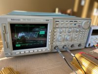
As an example - I tossed together a VERY quick and dirty comparison for a little cheap and cheerful benchtop switching PSU measured under identical conditions, but differing scope settings.
I used the dirty SE single probe method.
5V output with an 8ohm resistive load
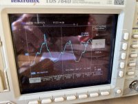
With probe settings mis-identified as 1x vs 10x, the scope simply provided the 10x differential in the measurement.
With the coupling impedance of the scope set to 50ohms instead of 1Mohms, the difference was also markedly different (pics below) - 50ohm was ~24mVrms of ripple and 94Vpp. 1M was ~85mVrms and 312mVpp
Bandwidth limiting to 20Mhz had a nominal effect on results, but made it easier to trigger etc.
Again... I am a complete and total novice... and I likely made several errors in my techniques.
The overall message, I suppose, is that I never look at the absolute value of the measurements. I simply check the relative measurements across my supplies using the same technique saved to (yes that's a floppy disk) the scope and pulled up each time.
Any input is always welcome as I learn and refine how I do this.
https://www.google.com/search?q=eev...#fpstate=ive&vld=cid:6ff682d5,vid:Edel3eduRj4
Attachments
Last edited:
EEVblog tutorials are terrific and very recommended. 👍
Ripple measurement is simple. Always use AC probe coupling with 1 MΩ input impedance. Connect probe ground to the PS ground and probe tip to measurement point (PS rail output). Take care not to accidentally connect probe ground to the rail, as that would blow fuses (inside oscilloscope or amplifier).
Oscilloscope will show rails AC waveform or ripple + noise. With strong noise coming from the switching PS, limiting oscilloscope bandwidth is helpful for getting stable waveform. Trigger settings also have options for noise rejection. You can try and play with those.
Oscilloscope will display on the screen measured peak to peak and RMS ripple values. RMS and PP values are directly related by simple math operation. Both values are good as absolute ones for comparison.
For all intents and purposes, you've outlined exactly how I've been doing it.
It's nice to know that for my uses, that's 'good enough'. It's far simpler, and the methods he uses and explains to further refine chasing the noise etc., are a bit over my head (at the moment). They'd require cobbling together (or buying) proper additional probes / attachments etc. My preference is 'close enough for government work'. 😉 I've tried the poor man's differential by using the math functions to subtract the two channels... it works; but it takes more time, and I'm more likely to screw it up over repeated measurements, since I don't do it that often.
With thanks!
Patrick
For some fun, and to show that I don't take great advice for granted... I did a quick and dirty measurement on a power supply that's in progress.
Linear supply.
Antek 4425
LT4320 Rectification
66kuF
Hammond 159ZJ
33kuF
0R155
33kuF
I only measured one rail.
Loaded w/24 ohm resistive load. 3, big 8 ohm dummy loads in series (It's what I had). I wanted to have a load, but not screaming hot resistors or an unrealistically low load. I'm still not sure how to load them properly, so I typically do unloaded and then approximate real-use current targets with resistors as a load.
Some odd high frequency stuff, that I'll assume is due to measurement technique / environment. PSUD sims lower, but who really knows? It's likely quiet enough. When I get it hooked to an amp, I'll do the standard distortion measurements and check the FFT.
Thanks again @tombo56!
Attachments
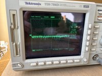
2.37mV RMS, looks like there's some ringing going on (unless I'm mistaken)
Perhaps a small value resistor after the 'L', 40V MLCC on the legs of the 4320? Traffo snubbers?
Perhaps a small value resistor after the 'L', 40V MLCC on the legs of the 4320? Traffo snubbers?
- Home
- Amplifiers
- Pass Labs
- CLC vs. CRC