Well, half of the message exceeds my english skill 😀 I understood the Patience, but nothing more 😀
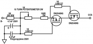
Eli is saying that the CCSs will total 6-7 mA, or 3 - 3.5 mA per section of the 12AT7. So the 100 ohm set resistor in the CCS will read 0.6 to 0.7 VDC across it, using the variable 10-turn pot to set it once it's up and running in the breadboarded amp.
Eli is saying (I think) that I was wrong to think you might want to run more current through the 12AT7. He's right.
The other part is about the voltage drop calculations that will be an estimate, not a final guarantee, of the voltages on the plates for the output valves and the 12AT7. You just won't know how the voltages will hold up under load until you have the thing wired up. Breadboarding means building the amp on the workbench with ample access to change things in and out while measuring. In other words, don't build this amp directly into a chassis yet. There are many things still pending, and you may need to change resistors, transformers, and other configurations. Many people use perforated pegboard.
For what it's worth, I think the El Cheapo CCS B- supply as shown in the schematic yields about -110 Volts under load into the two CCSs. Your build will be different if you use other transformers and a different mains voltage.
Also, if you are paralleling secondaries, it isn't really clear how you're hooking those up. Once you get the Antek transformer, you can redo the schematice to show the lead colors.
Wow this is not so easy anymore. Are you sure guys that it is worth the work, it will be better than an ST70? 😀 I am not questionning, and I am really happy that you guys help me. I really hope that somehow the amp will be complete, and it will be working. 😀
I am in love with this amp, even though it is not even made yet, and it is just in its design phase
I am in love with this amp, even though it is not even made yet, and it is just in its design phase
Obisix, be patient. Eli is a true mentor -- he will point you in a direction from which you will LEARN. He will not give you all the answers, but he will accompany you along your own path of discovery. IF you are serious about understanding and building a design-in-progress, and learning about electronics from it, you're in great hands here. If you're in a hurry, buy a kit or follow a proven schematic and a parts list.
Also, some others here can help with the schematic if you get stuck. Many people here can whip up schematics quickly. BUT it's good for YOU to keep correcting your own schematics. That way you learn more.
If you stick with this, your amp will be well-designed, within tube design limits for low distortion and have good sound. You won't be sorry. But you will need patience and you'll want to accumulate some basic tools for measuring, like a Digital Multi-Meter, alligator clip patch cables, wire nuts, wire cutters, small screwdrivers, pliers, and the like.
You're being pulled into a very rewarding hobby, and yes, you are wading into deeper waters away from shore. But Eli and many others here are strong swimmers who will be right next to you. (Will you take the plunge? It won't be as scary as you think, and it the result will be probably be better than any amp you've heard to date.)
Hang in there!
--Jeff
Last edited:
I Absolutely agree with you 🙂 I did not wanted to complain, I really love to learn! This September, I start Mechatronical engineering university, my second university! 🙂
OFF:
After the amp build, if you need something CNC engineered steel/wood, PM me and I'll make the faceplate/anything you want, you guys just have to pay me the materials+shipping and give me the image of the thing you want. I mean it!
ON:
Thanks for the encouraging words, it really helped me!
OFF:
After the amp build, if you need something CNC engineered steel/wood, PM me and I'll make the faceplate/anything you want, you guys just have to pay me the materials+shipping and give me the image of the thing you want. I mean it!
ON:
Thanks for the encouraging words, it really helped me!
Keep going on with the good work, some of us less knowledgeable lurkers are learning with you. You are the one guy in class asking the questions for others to scared to ask.
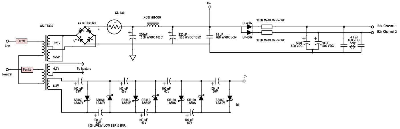
Using Schottky diodes, my guestimate is 7.5 V. per stage in a 1/2 wave parallel voltage multiplier that's energized by a 6.3 VAC winding. The bias (C-) supply should be capable of completely cutting the O/P tubes off. 7 stages should do the job. An additional Schottky stage works towards the B- rail. The final B- stage is a 6X4/EZ90 vacuum rectifier. That tube's heater is fed by the same 6.3 VAC winding as the voltage multiplier is fed.
50 PIV/1 A. Schottky diodes are definitely tough enough and few volts lower in the PIV rating is OK. 1/2 wave parallel multipliers are reasonably efficient. Everything has its price and here the WVDC rating of each multiplier stage's cap. has to increase. 100 muF. caps. in each Schottky stage should work out quite well, as that value is probably overkill. A 10 muF. cap. is used in the 6X4 stage
50 PIV/1 A. Schottky diodes are definitely tough enough and few volts lower in the PIV rating is OK. 1/2 wave parallel multipliers are reasonably efficient. Everything has its price and here the WVDC rating of each multiplier stage's cap. has to increase. 100 muF. caps. in each Schottky stage should work out quite well, as that value is probably overkill. A 10 muF. cap. is used in the 6X4 stage
Thanks Eli! By saying "muF", you mean microfarads, which are the same as "uF"?
Yes, muF. = μF. Depending on which computer is in use, I can or can't use characters other than Latin.
Now if Rongon will do some simulations of the multiplier stuff, we can begin to think about "breadboarding".
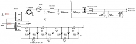
Well, I do understood the C- part, but not the B- part. what should be the plate voltage? 6.3V? I made the voltage multiplier for the C-, you can see it here.
Eli, if you would be so kind to explain the B- rail please, it would be perfect! 🙂
This is what I got:
Eli, if you would be so kind to explain the B- rail please, it would be perfect! 🙂
This is what I got:
Attachments
Now if Rongon will do some simulations of the multiplier stuff, we can begin to think about "breadboarding".
Oops, you caught me napping!
You're using the 6.3V winding for a voltage multiplier? Way cool. I'll see if I can get it to sim in LTspice...
This is the one, right? (On the 6.3V secondary at the bottom of the drawing)
http://www.diyaudio.com/forums/atta...sing-tube-amplifier-build-help-needed-psu.png
Forgive me if I'm missing something obvious, but where does this connect to 0V or ground?
I also have to put a load on the supply. What's the target? 6mA of current, or its equivalent resistance? Also, what's the target voltage for C-?
I'll be using an NXP PMEG6010AED as the Schottky diode, because it was the first 60V 1A Schottky model I found. I don't think there will be that much difference between different makes of diodes, do you?
--
Last edited:
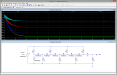
OK, here's a screenshot of the sim of the C- supply.
Unloaded (as shown), I get -42V DC, with about 300mV of ripple, peak-to-peak. That's about 100mV RMS?
I then put a 3k ohm load from C- to ground, to try to simulate a 12mA current draw (the cathode current of two 12AT7 LTP's, four triode sections). That puts the voltage at C- to -25.2V DC. Is that what you were aiming for?
--
Attachments
Last edited:
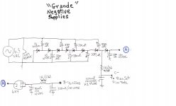
I've revised my thinking regarding the negative supplies. Remember, I upload "hen scratches", not pretty pictures. 
In this version, the vacuum rectifier only serves to slow B- rise. It is not part of the multiplier. I want to be absolutely certain that the 'T7 grids never become positive, with respect to the cathodes. Small signal triodes are most definitely not rated for a positive grid current regime.
OTOH, "instant" on is a GOOD thing in a bias (C-) supply.
Notice that the WVDC of each multiplier stage's cap. increases. The stress on the diodes is identical, but the stress on the caps. rises.
I don't think that 7.5 V. per multiplier stage is an unrealistic expectation. Yet larger caps., such as 470 or even 680 μF., in the multiplier could be a good thing. Use 105o C. rated parts that also have the highest allowable ripple current rating.
Attachments
Obisix,
Just wanted to comfort you in the design choice of the "El Cheapo Grande".
Be patient and work along under the guidance of Eli.
If fact the original "El Cheapo" was developped in a now exinct forum by Eli and some fellow tube enthousiasts as a joint group effort some years ago.
The development went over some months from the initial idea to the finished product.
For me it was one of the greatest reads on the Internet about the development of an amp. You eyewithnessed the birth of an amp so to speak.
Usually you see a guy coming up with the finished schematic without explaining the design decisions that have been taken.
The "El Cheapo" development was different, each week some progress was made. Sometimes an unexpected problem had to be solved.
Eli provided some insights, commented the measurements of a build in progress, etc...
In the end this experience was far more rewarding for all the participants (stealth readers like me included) than building an amp according to
an old schematic. (Yes, in the aftermath of this process, i built an El Cheapo too.)
So, my advice is : go ahead, hang on this unique opportunity and built it. Be sure to post some photos of the build phase.
You'll see that this will inspire other builders too. I've seen it with the El Cheapo and the Baby Huey from Gingertube (I built that one too).
If you are among the first builders, your learing experience will be more intensive because of the feedback you give and influence you could have on the design.
Be bold and ask questions, even if they seem stupid to you. Both mentioned projects lived on the questions being asked and answers given.
I'd like to thank Eli for "mentoring" this development and investing his time and patience in it. (that counts "retroactively" for the El Cheapo too).
Kind regards,
Yves
Hey Eli,
I like your thinking on the C- and B- supplies. I'll throw it into LTspice this evening, to see what the program has to say about it.
I like the easy/simple way you get a slow start for the B- to the 12AT7 tail CCS's, while keeping a quick-start for the C- bias supply. I wish I had thought of that.
--
Well I made it to make the schematic, altough I have some questions:
Wouldn't the diodes voltage rating rise as well as the capacitor ratings?
Only the 100 uF capacitor has to be KZ Muse type capacitor?
I don't see any trimpots near C-... where should it be?
Is the B- cathode voltage has 8 stages of multiplying before it? Is that correct?
I made something differend though:
I used only 200V caps in the voltage multiplier, as it is really cheap here in Hungary, I can use a lot of them.
Super excited! 😀
Attachments
Last edited:
Sebastian,
It certainly is OK to use 'lytics whose WVDC is greater than a situation requires. However, there are items of concern. High WVDC parts occupy more physical space. What is the temperature rating of the parts? 105o C. parts will last longer in the heat of a tubed amp. What is the equivalent series resistance (ESR) of the parts? I said look for high ripple current rated parts, as that goes hand in hand with a highly desirable low ESR.
Even if you build with overrated parts, please put the "correct" values in the schematics. Other, future, builders will see accurate information.
Nichicon KZ series (Muse) electrolytic caps. have repeatedly demonstrated good performance, when in the signal path. The reservoir cap. of a bias supply is (you guessed it) in the signal path.
I leave it to the experts at VMI to explain the ins and outs of voltage multiplier operation.
Well I made it to make the schematic, altough I have some questions:
Wouldn't the diodes voltage rating rise as well as the capacitor ratings?
Only the 100 uF capacitor has to be KZ Muse type capacitor?
I don't see any trimpots near C-... where should it be?
. . .
I don't want to speak out of turn or stand in for Eli, here, but I have recently worked with a similar supply. You put the trim pots between the C- output on the supply and the 330KOhm grid resistors on the amp schematic (where you have labeled C- between the output tubes).
If you have matched pairs of 7591s, you can do one trim pot per channel, as I just described. If you want super control over matching the currents for each PP pair, you can put a trim pot at each grid for all four tubes. That may be overkill here unless you are not getting matched pairs.
Since there is little to no current at the grid, you will need to figure out the most likely value for the trim pot total resistance. You will want to strike a useful range of output voltage on the wiper of the pot. You'll want some room on the "ends" of the pot, with the wiper in the middle range for actual use. You know that the B- section at "A" in Eli's drawing will draw about 12 -14 mA plus a little for losses, and you have a 1KOhm final resistor in front of the C- takeoff point. Once you know the preferred bias voltage for the 7591A (16-18V or so on each grid for this hybrid bias scheme??), and the actual voltage at C- with the B- loaded, you can start to calculate the pot as a voltage divider.
This may sound complex, but you can get close enough fairly easily. You can breadboard these C- and B- supplies and load the B- with enough resistance to simulate 12-14 mA and then go from there to figure a good middle value for the pots, using the actual output voltage at C-. You will want to build a loop through the bias pots that returns to ground, passing a small value of current (1 - 2 mA). The wiper becomes the voltage divider and runs to the grid resistors. Use high wattage resistors for loading the B- supply, since they will get warm! You can parallel or series what resistors you have on hand to configure this bench test. For starters, if you aim for about 25VDC at 15 mA, you get about 1.8K for a load resistance, less if the goal is higher voltage.
Regarding the diodes, as long as they are rated well over the output voltage, just use the same ones throughout the C- supply. I would think that 50-100V PIV Schottkys would do fine if we're looking at a 30-40 VDC supply. Eli mentioned 50V PIV earlier in the thread.
Last edited:
Oh, and for the bias pot loops, note that since you're returning to ground, the pots will be in parallel with respect to the C- output and ground. Consider than when sizing them for a given current choice in the loops and your desired voltage range.
25 PIV diodes would probably be quite fine in the multiplier. (6.3) (21/2) = 9.3, which does not look threatening to me.
Only a single trim pot. is needed in each channel, for this combination biased setup. The RC bias network each PP pair "stands" on compensates for minor cathode current imbalance. PP O/P tube pairs MUST be closely matched in the gm dept., but biasing arrangements impact on how closely cathode current needs to matched.
The total B- draw is 12 mA. If C- draw reaches 4 mA., it will be a surprise. A 50 V. rail and a 50 Kohm trim pot. works out to 1 mA. 😉
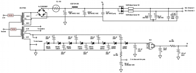
Well guys, this is the capacitor I tought about: Panasonic Capacitor.
I certainly know that there will be enough space for everything, you don't have to worry about it 🙂
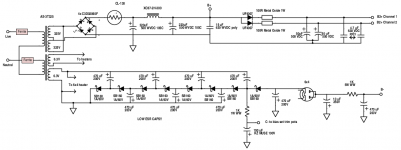
Also, I modified the El Cheapo Grande Schematic in a way that the trim pot is now inside that!
See everything you guys made up until now! If there is something, please let me know, in terms of capacitors.
Also, another question: What happens if the cap. I use has no high ripple current rating, it is low?
I certainly know that there will be enough space for everything, you don't have to worry about it 🙂
Also, I modified the El Cheapo Grande Schematic in a way that the trim pot is now inside that!
See everything you guys made up until now! If there is something, please let me know, in terms of capacitors.
Also, another question: What happens if the cap. I use has no high ripple current rating, it is low?
Attachments

- Home
- Amplifiers
- Tubes / Valves
- Choosing a tube amplifier to build, HELP needed