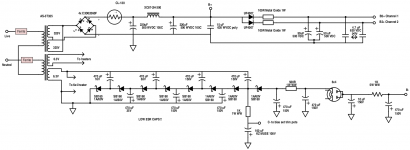
I would take this to mean that you need a final decoupling RC network after your last 470 muF capacitor, before the 6X4. I'm not sure what the best values would be off the top of my head, but you would drop six volts with a 500 Ohm resistor (500 Ohms x .012 Amp). A 1KOhm would seem to drop more than I would be comfortable with, but Eli and others may be fine with that. You could combine that with another of your 470 muF caps if you have several. A 100 muF cap might be okay, but I haven't figured the math.
If, after adding this additional decoupling network, the voltages are all too low to run the bias and/or the CCS, then add more stages to the multiplier.
--Jeff
If, after adding this additional decoupling network, the voltages are all too low to run the bias and/or the CCS, then add more stages to the multiplier.
--Jeff
Last edited:
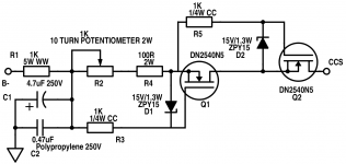
The second part of what Eli said is rather complex to answer clearly but in short, there is a certain negative voltage that has to be applied to the junction of the 330k grid leak resistors. Let's assume this is -10volts. What Eli is saying is that -10v should not be obtained where the trimpot is at the ends of the adjustment. Ideally it should around the middle. To allow this adjustment, C- should be around -20v. Subsequently where you tap the voltage multiplier should produce around -20v. This is not necessarily where it is shown on your schematic.
First, you need to know what voltage you need on C-
To know what voltage should be on C-, you need to know how Eli/you want(s) to run the output tubes.
I will try to give you an idea:
First, the way the 7591's screen grid is connected to taps on the output transformer is called ultra-linear operation.
If i have to guess, Eli is going for the operation design on the spec sheet like below:
425volts plate supply voltage looks in line with your 325v transformer secondary. (325VAC * 1.414 = 460VDC, taking account some voltage drop on the CL-130 and choke, perhaps we should arrive at something close to 425VDC).
Now, your design is a mix between fixed bias (because you have C- as bias voltage on the grid) and cathode bias (because you have the 100R cathode resistor, this should be 185R if your amp is following the cathode bias design above).
Now, here comes the fun part.. MATH. Cathode bias means the grid is at zero volts and the tube is biased by elevating the cathode voltage by applying cathode resistor. How high is the cathode voltage? Notice that plate current at idle is 88mA. This is for one tube. There is a pair of 7591 tube having one common cathode resistor. This means at the top of the 185R resistor, there should be (88mA x 2) * 185R = 32.6V. Again, per spec sheet design above, this assumes cathode bias operation.
Since your cathode bias is only 100R, the voltage developed is only (88mA x 2) * 100R = 17.6V. This means there is difference of 17.6V-32.6V = -15VDC. This is what should be on the junction of the 330k grid resistors. Per Eli's suggestion, C- should then be around -30 VDC.
There are many ways to get this -30VDC from 6.3V heater winding. Your (and Eli's) way is to have a voltage multiplier. 6.3VAC rectified to DC is approx 8.9VDC (ignoring voltage drop on the diodes). 30VDC is about four times of 8.9VDC. This means you need voltage quadrupler. Google this and there you have designs for how much diode+cap combination you need on the multiplier.
How i would do it is perhaps lazier. I would rectify the 6.3VAC to DC with fullwave rectifier and add perhaps 100uF filter capacitor. From there, i will feed it to some boost converter to increase the 8.9VDC to 30VDC. Here is one example:
DC DC 4 5 32V to 5 52v XL6009 Boost Step Up Module Power Supply LED Voltmeter | eBay
To know what voltage should be on C-, you need to know how Eli/you want(s) to run the output tubes.
I will try to give you an idea:
First, the way the 7591's screen grid is connected to taps on the output transformer is called ultra-linear operation.
If i have to guess, Eli is going for the operation design on the spec sheet like below:
An externally hosted image should be here but it was not working when we last tested it.
425volts plate supply voltage looks in line with your 325v transformer secondary. (325VAC * 1.414 = 460VDC, taking account some voltage drop on the CL-130 and choke, perhaps we should arrive at something close to 425VDC).
Now, your design is a mix between fixed bias (because you have C- as bias voltage on the grid) and cathode bias (because you have the 100R cathode resistor, this should be 185R if your amp is following the cathode bias design above).
Now, here comes the fun part.. MATH. Cathode bias means the grid is at zero volts and the tube is biased by elevating the cathode voltage by applying cathode resistor. How high is the cathode voltage? Notice that plate current at idle is 88mA. This is for one tube. There is a pair of 7591 tube having one common cathode resistor. This means at the top of the 185R resistor, there should be (88mA x 2) * 185R = 32.6V. Again, per spec sheet design above, this assumes cathode bias operation.
Since your cathode bias is only 100R, the voltage developed is only (88mA x 2) * 100R = 17.6V. This means there is difference of 17.6V-32.6V = -15VDC. This is what should be on the junction of the 330k grid resistors. Per Eli's suggestion, C- should then be around -30 VDC.
There are many ways to get this -30VDC from 6.3V heater winding. Your (and Eli's) way is to have a voltage multiplier. 6.3VAC rectified to DC is approx 8.9VDC (ignoring voltage drop on the diodes). 30VDC is about four times of 8.9VDC. This means you need voltage quadrupler. Google this and there you have designs for how much diode+cap combination you need on the multiplier.
How i would do it is perhaps lazier. I would rectify the 6.3VAC to DC with fullwave rectifier and add perhaps 100uF filter capacitor. From there, i will feed it to some boost converter to increase the 8.9VDC to 30VDC. Here is one example:
DC DC 4 5 32V to 5 52v XL6009 Boost Step Up Module Power Supply LED Voltmeter | eBay
Last edited:
Following up what Ballpencil wrote, yes, you are likely to have to prototype on the bench, first with best-guess figures and then with measurements under actual operation. The data is available to think this through, as Ballpencil points out, using Ohm's law and using values from the tube datasheets and your bias circuits. Start from wiper center point of the pots for figuring the pot resistance. You want the additional "wiggle room" in the pots because tubes vary in how much actual current they pass for any given bias and plate voltage.
You could easily prototype the C- multiplier, load it with the B- supply along with a 12 mA draw, and then while it's running, tap each stage on the C- supply and record the various voltages to ground. Then you'll know the best likely stage to tap. If there is insufficient voltage (Ballpencil suggests -10V), you can add extra cap/diode multiplier stages.
You could easily prototype the C- multiplier, load it with the B- supply along with a 12 mA draw, and then while it's running, tap each stage on the C- supply and record the various voltages to ground. Then you'll know the best likely stage to tap. If there is insufficient voltage (Ballpencil suggests -10V), you can add extra cap/diode multiplier stages.
Last edited:
Remember, my guesstimate is 7.5 V. per stage in the voltage multiplier. BP and Jeff are correct, in that experimentation is needed to find the optimum stage to tap the multiplier as the C- (bias) takeoff point.
Look more towards the "fixed" bias operating condition sets on the 7591 data sheet, as the bulk of the total bias comes from the C- supply. Regardless of how the g1 bias is obtained, the potentials on the various electrodes (in relation to each other) control what's going on.
Look more towards the "fixed" bias operating condition sets on the 7591 data sheet, as the bulk of the total bias comes from the C- supply. Regardless of how the g1 bias is obtained, the potentials on the various electrodes (in relation to each other) control what's going on.
Wow thank you guys!
Then I can order the transformers for prototyping? The O/P Transformer, the choke, and the power supply transformers are sure?
I will do it as you guys said!
Eli. Is there any way of using that module BP posted? 😀 Sounds easier for me!
Thank you guys for your patience, I will provide every information when prototyping 🙂
Before proceeding any further, may i suggest putting reference designator for each component? Saying "junction of 330k grid leak resistors" is harder than perhaps "junction of R10 and R11". This should avoid ambiguation as well.

Bump.. Just finished a festival here in Hungary, sorry for being inactive!
So everything is okay on the schematics? 🙂
So everything is okay on the schematics? 🙂
The 500 Ohm /470 muF decoupling network right before the 6X4 was my start-with-a-guess for the values. You don't need such a large capacitor (I think you said you had a bunch of 470 muF on hand), and if you need to recapture more voltage for B- in actual use, you may need to drop that 500 a lower value. (At 500 Ohms, you'll drop 6 V at 12 mA, and the tube rectifier will drop some more.)
This is where you prototype on the bench and measure and then try other values until you have what you need to power the Constant Current Sources.
Keep us posted!
--Jeff
This is where you prototype on the bench and measure and then try other values until you have what you need to power the Constant Current Sources.
Keep us posted!
--Jeff
Okay then, if no one is against it, I'll order the PSU and the Edcor transformers, and will come back when I got them!
Thank you guys, I'll keep you updated!
Thank you guys, I'll keep you updated!
Hi Sebastian,
I am following along your build with great excitement. I would like to replicate it once you have a successful and wonderful sounding amp.
Keep us updated and your progress. And of course with photos and the latest schematics!
I am following along your build with great excitement. I would like to replicate it once you have a successful and wonderful sounding amp.
Keep us updated and your progress. And of course with photos and the latest schematics!
If you would like to investigate SET amplifiers the Randall amp on the One Electron site is a good design. Hugh Dean told me recently he was very impressed when hearing a Cary SET.
I have built and auditioned a lot of classic solid state amps, but I am tempted to try out a SET design.
I have built and auditioned a lot of classic solid state amps, but I am tempted to try out a SET design.
Things are in change
Things are in change...
So I was about to order my transformers, when a sound engineer friend of mine gave me a contact.
This is a 50-60 year old man, and he is a transformer winder master, he has been doing it for 30 years now, and having better and better results!
I am thinking of oredring my transformers from him, as it is much less expensive, and since it is handmade, it would be nice aswell! He is doing output transformers and power transformers aswell.
The question is for Eli mainly, but any opinion is welcomed!
If I'm about to order the power transformer, I can set any voltage and any amps there. wouldn't it be perfect if I would order the transformer with 2x325V, 1x6.3V and another secondary at a higher voltage for the C- and B-?
If so, what this voltage, and amperage should be?
If I'm about the order the O/P Transformers from him, what informations shoul I give him regarding the informations? Is is sufficent to add just the informations of the Edcor transformer I was about to use, provided on the website? If not, what else should I add?
I would be happy if you guys could answer those questions, mostly Eli!
I'm really happy about this, since it would cut the costs!
I am not starting to buy anything else until I don't find the proper transformers! 🙂
Thanks for the help again guys!
Sebastian,
Give me a few days to try and round up some old notes. With a custom power trafo, the complexity of the negative PSU will lessen.
The parameters for the O/P "iron" are well established. You need a 6.6 Kohm primary and a 4 ohm secondary. 60 W. of power handling is also needed. Magnetic headroom to support the GNFB is required.
Okay, thank you!
Although, I sold my Tannoys a week ago, and bought a pair of Monitor Audio Bronze II, I really loved the sound better!
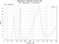
Actually I still do think that the amplifier would work with it aswell, just the impedance curve is different. I attached it!
Eli. My guesses are correct that I won't have to change anything else but the secondary impedance of the O/P transformer up to 8 ohms?
Sorry about the changes, but I liked the Bronze II so much better than the tannoys.
Although, I sold my Tannoys a week ago, and bought a pair of Monitor Audio Bronze II, I really loved the sound better!
Actually I still do think that the amplifier would work with it aswell, just the impedance curve is different. I attached it!
Eli. My guesses are correct that I won't have to change anything else but the secondary impedance of the O/P transformer up to 8 ohms?
Sorry about the changes, but I liked the Bronze II so much better than the tannoys.
Attachments
Am I correct that the impedance of those speakers dips down to as low as 3.5 ohms, and then rises to over 14 ohms? That's going to be a bit of a beast to drive with a tube amp. The amp will definitely need a goodly amount of loop negative feedback to get the output resistance down, which hopefully will keep it from sounding peaky at the impedance peaks (especially that one at about 2.5kHz, which could sound really shrill). It might be better to treat this speaker as a 4 ohm speaker, and design the amp to have as high a damping factor as possible.
I once had a pair of B&W DM100 speakers that sounded really, really smooth with an amp like an NAD 3020, but absolutely shrieky and nasty with a push-pull 2A3 (no gNFB) amp. The speaker's impedance curve was undoubtedly much too peaky for the tube amp. I suppose adding gNFB to the tube amp would have helped with that particular problem, but I wasn't into doing that at the time.
I'll be interested to see what comes of this. I have an old Scott integrated amp that uses 7591's but is beyond repair, but its transformers are good...
--
- Home
- Amplifiers
- Tubes / Valves
- Choosing a tube amplifier to build, HELP needed