Sebastian,
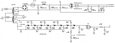
Please correct the PSU schematic to show the WVDC numbers I indicated. What you actually use is your business. Panasonic TS-ED series caps. are wonderful. Notice that the data sheet says high ripple current. 🙂
The bias set trim pot is incorrect. The wiper connects to the junction of the 330 Kohm resistors. An end of the pot. connects to C-, while the other end is grounded. The pot. is an adjustable voltage divider.
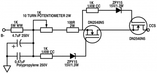
As the B- rail in this amp is "shorter" than that in the original "12" W. tube "El Cheapo", make the value of the CF thermal isolator between the LTP cathodes and the CCS 100 Ω.
Please correct the PSU schematic to show the WVDC numbers I indicated. What you actually use is your business. Panasonic TS-ED series caps. are wonderful. Notice that the data sheet says high ripple current. 🙂
The bias set trim pot is incorrect. The wiper connects to the junction of the 330 Kohm resistors. An end of the pot. connects to C-, while the other end is grounded. The pot. is an adjustable voltage divider.
As the B- rail in this amp is "shorter" than that in the original "12" W. tube "El Cheapo", make the value of the CF thermal isolator between the LTP cathodes and the CCS 100 Ω.


For the same reason as the thermal isolation part's value was reduced, the value of the 5 Kohm WW resistor in the CCS schematic block also has to be reduced. However, I'm not quite ready to take a stab at a new value.
Overall, things are looking pretty darned good.
Overall, things are looking pretty darned good.
OK, let's go with 1 Kohm, instead of 5 KOhms, in the the CCS schematic block. A stage or 2 can always be added to the voltage multiplier, if necessary.
An important point is that the voltage on the 6X4's cathode must be "shorter" than -100 V. A 6X4's heater can be no more than 100 V. positive, with respect to the cathode. The 6X4's heater is at ground (0 VDC).
An important point is that the voltage on the 6X4's cathode must be "shorter" than -100 V. A 6X4's heater can be no more than 100 V. positive, with respect to the cathode. The 6X4's heater is at ground (0 VDC).
Last edited:


Hi Obisix,
All indirectly heated tubes have a limit to how much potential difference is allowed between its heater and cathode. In 6X4 case, if the heater is tied to ground, then the cathode voltage can not be MORE than 100v or LESS than -100v. I believe this prevents arcing between the heater and cathode (like on spark plug in internal combustion engines).
All indirectly heated tubes have a limit to how much potential difference is allowed between its heater and cathode. In 6X4 case, if the heater is tied to ground, then the cathode voltage can not be MORE than 100v or LESS than -100v. I believe this prevents arcing between the heater and cathode (like on spark plug in internal combustion engines).
So that means that I'll have to ground the filament supply of 6.3V, or just leave it as it is right now? 😕
So that means that I'll have to ground the filament supply of 6.3V, or just leave it as it is right now?
As shown, your filament supply is already at ground level (notice that one end of the transformer's 6.3v supply is tied to ground?) but since your cathode is (or could be) at voltage less than -100v, you risk the arcing i told you earlier. You need to check what is the voltage at the 6X4 cathode first. Label all the important voltages while you're at it, like the B+, B2+, B- and C-.
Unfortunately, if you do exceed the 100v difference, this means you can not use the same winding to power the 6X4 heater and the voltage multiplier. What you need to do here is use a separate winding for the 6X4 heater where you tie the winding to some voltage that stays within 100v difference from the cathode. One way is that you join one end of the 6.3V winding directly to the 6X4 cathode, this gets you 0v difference between the heater and cathode..
Read about the heater elevation here The Valve Wizard
Last edited:
Sebastian,
One side of the 6.3 VAC winding feeding the negative supplies multiplier is grounded and that winding also energizes the 6X4 heater.
As ballpencil stated, the 6X4 data sheet indicates that the heater can't be more than 100 V. positive, with respect to the cathode. The heater is at 0 VDC (ground). Therefore, -100 V. is THE limit for the cathode and a margin of safety is highly desirable.
The 100 Ω 7591 cathode bias resistor is a 1 % part, as it serves as the current set test point. A 5 W. rating will not provide fusing action that can save the tubes, should they go "bonkers". As 100 mA. passed through 100 Ω dissipates 1 W., look for a 2 W./1 % part. A 1 W. part could fail, when a legitimate musical transient is played. A balance has to exist between protecting the O/P tubes and unnecessary failure of the cathode bias resistor. Frequent "popping" is unacceptable.
Thanks Ballpencil, and Eli for the kind words!
This was really helpful for me, but it started to worry me, what will happen if it exceeds the limit? Will there be any way of making this correctly?
You're right Eli, forgot to change wattage, gonna do it tomorrow!
This was really helpful for me, but it started to worry me, what will happen if it exceeds the limit? Will there be any way of making this correctly?
You're right Eli, forgot to change wattage, gonna do it tomorrow!
This was really helpful for me, but it started to worry me, what will happen if it exceeds the limit? Will there be any way of making this correctly?
It is necessary for the designer (me) to heed published warnings. I do heed the warnings and left some "breathing room". Also, that GE data sheet used the Design Maximum System, which means exactly what it says, don't exceed these limits in a design. In fact, the tube can take a bit more, but it's foolhardy to go there, on purpose.
Three ratings systems can be found in the data sheet library: the very conservative Design Center, the Design Maximum, and the Absolute Maximum.
Sebastian,
Also chirping in now and then; you are in good hands - all 8 of them! As said before, just keep on. In no time, you will be doing what Eli has done here - er - well almost. Like driving a car: At first one concentrates, carefully negotiating every turn - later you talk all the way through a city, being rather surprised that you are suddenly home.
Also as said, go on the internet and read some of the many good basic sites on tube workings. (Don't tell anybody; I also do the same now and then ....)
I traced Rongon's steps*. Sebastian, even if the heater voltage should go to 7V because of a mains surge (by which time the tubes would have burnt out), the voltage at the 6X4 cathode will have been no higher than -50V. So sleep soundly; before the discussed heater-cathode voltage would reach danger level, all else (including your household utensils) would have gone up in smoke. It is the safest limit around here!
*Rongon: NOT checking up on you! We researchers are such curious animals, repeat things. I wanted to also look at other matters.
Also chirping in now and then; you are in good hands - all 8 of them! As said before, just keep on. In no time, you will be doing what Eli has done here - er - well almost. Like driving a car: At first one concentrates, carefully negotiating every turn
- later you talk all the way through a city, being rather surprised that you are suddenly home.Also as said, go on the internet and read some of the many good basic sites on tube workings. (Don't tell anybody; I also do the same now and then ....)
..... but it started to worry me, what will happen if it exceeds the limit? Will there be any way of making this correctly?
I traced Rongon's steps*. Sebastian, even if the heater voltage should go to 7V because of a mains surge (by which time the tubes would have burnt out), the voltage at the 6X4 cathode will have been no higher than -50V. So sleep soundly; before the discussed heater-cathode voltage would reach danger level, all else (including your household utensils) would have gone up in smoke. It is the safest limit around here!
*Rongon: NOT checking up on you! We researchers are such curious animals, repeat things. I wanted to also look at other matters.
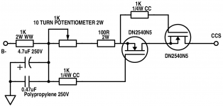

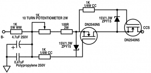
One thing to consider on the MOSFETs in the CCS is a protection Zener diode, 15V, 500mW to 1W, from source to gate. While it's not absolutely necessary, it may help with static discharges and "thumps" or, ahem, cough-cough, inadvertent electrical mishaps like disconnecting and connecting cables and subwoofer amps while music is playing . . .
You can also use two, in series back-to-back.
You can also use two, in series back-to-back.
Attachments
Last edited:
Sebastian,
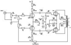
I said make the PP pair cathode bias resistor 2 W./1%. That specific spot has to compromise between reliability and providing some protection against O/P tube runaway.
Use the P = I2R formula to work out how much power is being dissipated in other resistor positions. You want a substantial margin of safety in the rating of parts, except in unusual situations. For instance, a resistor will dissipate 0.4 W. Use at least a 1 W. part.
"Standard" wirewound resistors are somewhat inductive. That inductance makes them slightly more effective than non-inductive parts in PSU RC filter sections. To get wirewound parts for a specific position, it may be necessary to use higher wattage than would otherwise seem indicated.


It may very well be necessary to isolate the 6X4's cathode from the voltage multiplier. A RC filter section would do that. It's no big deal to add additional stages to the multiplier, if sufficient volts to operate the CCS and LTP are not present.
There is nothing sacrosanct about where the multiplier is tapped to get the C- voltage. The best stage for tapping could be different than that shown in the schematic. The best tapping location allows for easy control of 7591 "idle" current. The bias trim pots. should not end up with their wipers close to either end. "Hair trigger" controls, of any sort, are not a good thing.
There is nothing sacrosanct about where the multiplier is tapped to get the C- voltage. The best stage for tapping could be different than that shown in the schematic. The best tapping location allows for easy control of 7591 "idle" current. The bias trim pots. should not end up with their wipers close to either end. "Hair trigger" controls, of any sort, are not a good thing.
- Home
- Amplifiers
- Tubes / Valves
- Choosing a tube amplifier to build, HELP needed