O.K.REW uses a digital filter to get good SNR
And what level is -80dBfs on your generator in Volts ?
Hans
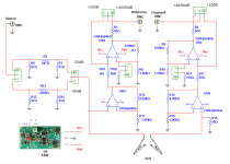
If you are going to put it in parallel shouldn't you drive it with a current source instead of a voltage source? A voltage source has no resistance, it is a short circuit.
Thank you Ray. I tried it on the sim. I don’t see dramatic changes. But how can I do it on the bench?
Up to now,
The signal generator I have used on the bench has an Ro of 50 Ohm.
The soundcard has an Ro of 150 Ohm.
The voltage source in the simulation has an R0 of 50 Ohm.
George
Attachments
George,Thank you Ray. I tried it on the sim. I don’t see dramatic changes. But how can I do it on the bench?
Up to now,
The signal generator I have used on the bench has an Ro of 50 Ohm.
The soundcard has an Ro of 150 Ohm.
The voltage source in the simulation has an R0 of 50 Ohm.
George
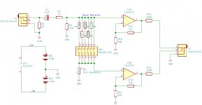
Your circuit diagram with current source in / transimpedance out is correct but as you say difficult to realise.
The equivalent version is with voltage source in / voltage sense out with the Cart in series with the 47K/250pF, not with a transimpedance as in #455.
Hans
With voltage source plus transimpedance you measure the current through the Cart, but the 47K//250pF is playing no role because of the virtual gnd input of the transimpedance.
For measuring the impedance of the Cart only, that's O.k., but when you want to include the termination load in the equation, than you will need a voltage sensing amp.
Hans
For measuring the impedance of the Cart only, that's O.k., but when you want to include the termination load in the equation, than you will need a voltage sensing amp.
Hans
If you don’t care about the 47k//250pF and just want to concentrate on the Cart impedance, yes.Thank you Hans.
So you suggest I continue testing the way I was doing till now
George
0dBfs is +/-1V peakO.K.
And what level is -80dBfs on your generator in Volts ?
Hans
Thanks, that would then be 0.75Vrms, or 0 dBU.0dBfs is +/-1V peak
Hans
David,
I owe you an apology.
Because of switching signals in the computation in #451, I though your design was corrupting the phase, which I found was not the case as later shown in #457.
Further Simulation now showed that your design is perfectly able to calculate the inductance of the Cart's coil with very low voltages, deep down into the uV region.
I'm eagerly waiting to see your results.
Succes.
Hans
This has been an excellent demonstration of how it is so easy to end up measuring your test setup, rather than the test device.
My opinion is that using 50 Ohm world RF test equipment to measure 50k impedances is even less likely to work as planned.
My opinion is that using 50 Ohm world RF test equipment to measure 50k impedances is even less likely to work as planned.
Let's face it, it's a tricky challenge anyways at the signal levels we're interested in. Quite possibly means it's not been done before, at least in a cartridge environment. Which ought to inspire, I think.This has been an excellent demonstration of how it is so easy to end up measuring your test setup, rather than the test device.
My opinion is that using 50 Ohm world RF test equipment to measure 50k impedances is even less likely to work as planned.
There's not much current to sense and measure, around the 1nA range, when coil impedance has 100uV excitation. I think that's the way to look at the problem perhaps. Or the other way round, sense coil voltage at (very small) constant amplitude ac current.
LD
Last edited:
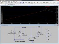
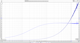
Well I think that I have got to the point that I can measure impedance and phase up to 20Khz and impedances up ~100k at level down to -80 and maybe even -90 dBU
So far I find that there is no inductance or resistance variation over the audio dynamic range and that the classical L-R-C model is valid for my old Goldring C1042 cartridge
So far I find that there is no inductance or resistance variation over the audio dynamic range and that the classical L-R-C model is valid for my old Goldring C1042 cartridge
Dave,Well I think that I have got to the point that I can measure impedance and phase up to 20Khz and impedances up ~100k at level down to -80 and maybe even -90 dBU
So far I find that there is no inductance or resistance variation over the audio dynamic range and that the classical L-R-C model is valid for my old Goldring C1042 cartridge
Could you be so kind to tell the input level for making the recording in #470 and the filter BW (1/48 octave ?) that was used for measuring magnitude and phase.
Hans
The level at the REW impedance jig input, after input attenuation, was -40dBU. This drove the cartridge through a 5k1 sense resistor.
The bandwidth is unknown, REW does a slow frequency sweep, which in this case was 1M. There is some sort of averaging going on. Slower sweeps give better SNR.
SNR gets worse at high test impedances as the voltage across the sense resistor gets smaller and smaller.
A potential source of phase error is timing offset between Left and Right ADC inputs.
In my jig I found a small error appearing at 20kHz of a few degrees.
Hi Dave,The level at the REW impedance jig input, after input attenuation, was -40dBU. This drove the cartridge through a 5k1 sense resistor.
The bandwidth is unknown, REW does a slow frequency sweep, which in this case was 1M. There is some sort of averaging going on. Slower sweeps give better SNR.
SNR gets worse at high test impedances as the voltage across the sense resistor gets smaller and smaller.
A potential source of phase error is timing offset between Left and Right ADC inputs.
In my jig I found a small error appearing at 20kHz of a few degrees.
Do I understand you correct, -40dBA after the 1K/33 Ohm input attenuation ? This would then mean approx 6.6mV on the Cart at 3 Khz, right ?
Hans
Roughly yes:
DAC output is -10dBU
Input attenuation = 30 dB
So voltage at sense resistor = 10mV peak, 7mVrms
Voltage on cartridge = 5.8mVrms at 3kHz
DAC output is -10dBU
Input attenuation = 30 dB
So voltage at sense resistor = 10mV peak, 7mVrms
Voltage on cartridge = 5.8mVrms at 3kHz
Hi Davidsrsb I've been waiting to find time to properly work through your recent stuff, and still not there yet. Every encouragement, the action begins perhaps -30dB below that, if it happens at all, IMO. Appols if already covered.Roughly yes:
DAC output is -10dBU
Input attenuation = 30 dB
So voltage at sense resistor = 10mV peak, 7mVrms
Voltage on cartridge = 5.8mVrms at 3kHz
LD
- Status
- Not open for further replies.
- Home
- Source & Line
- Analogue Source
- Cartridge dynamic behaviour