I think you're right, Hans.Hi Jack,
That would be a shame, when resolution turns out to be the deal breaker.
The HP3577 spec's are a bit vague on that, but they mention that at levels between -90 dB to -100dB below Full Scale Input, resolution with 10Hz BW is still +/-0.75dB.
When taking +15dBm or 1.26V as Full Scale input, -100dB would be 12.6 uV.
That is still- above the 22uV that I was suggesting with the -40dBm setting + 40dB attenuation with 5K - 50 Ohm.
So do I make a wrong interpretation of the spec's ?
Hans
The problem is that the coil is such an impedance mismatch that only a tiny fraction of the 0.8mV output at -49dBm reaches the input (which is terminated by 50R). At 10kHz perhaps only 1uV or so. Whereas the full 0.8mV appears across the coil. That is the crux of the problem.
The resolution of the 3577A is up to it, as you say, toward the 10's of uV. But at the same time, we need that order of excitation potential to be across the coil. That's why 40dB attenuators (easy) and 40dB amplifiers (achievable) are needed. As Scott says, a few hundred kHz of bandwidth should do it, GBW of 20MHz or less with a bit of compromise. Within the scope of opamps with a bit of care. Or pentodes 😎
LD
LD, you are right.I think you're right, Hans.
The problem is that the coil is such an impedance mismatch that only a tiny fraction of the 0.8mV output at -49dBm reaches the input (which is terminated by 50R). At 10kHz perhaps only 1uV or so. Whereas the full 0.8mV appears across the coil. That is the crux of the problem.
The resolution of the 3577A is up to it, as you say, toward the 10's of uV. But at the same time, we need that order of excitation potential to be across the coil. That's why 40dB attenuators (easy) and 40dB amplifiers (achievable) are needed. As Scott says, a few hundred kHz of bandwidth should do it, GBW of 20MHz or less with a bit of compromise. Within the scope of opamps with a bit of care. Or pentodes 😎
LD
With the setup I proposed, one side has 22uV, but the other side has only 37nV@10Khz, drowned in the 70nV noise of the input.
That was my thinking error.
The Johnson noise produced by the cart plus network at the low side lies at 910pV/Sqrt(Hz), mainly caused by the 50Ohm resistor and still 32dB below the generated signal.
With a 40dB Amp at the low side to compensate the 5K/50Ohm at the other side, this amp has to produce at the most a few nV noise within a 10Hz BW, which should be possible with a standard Riaa MC preamp giving some 40dB gain at 10Khz.
Alternatively, an MC preamp could be transformed in a straight 40dB amp.
With 3.7nV Noise with 10Hz BW, we have 20dB SNR, giving a max phase error of 5degrees and a magnitude error of 1dB.
Of course when turning the -40dBm to a higher level, this improves rapidly.
Hans
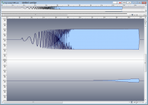
To return to my something completely different experiment. I tried simulating the cartridge model in a completely different way. I added a weakly coupled flux to the coil as the stimulus and as expected I got the constant velocity response out since a SPICE source is constant amplitude. I was hoping to prove that sensing the voltage on the unloaded coil gave the same relative amplitude of voltage out as when loaded with 47k||100pF. Everything seems to work as expected but now no noise or frequency response of the loading and the coil has -30dB of the current.
Time to try my 10M||1pF buffer in the headshell.
Time to try my 10M||1pF buffer in the headshell.
Instead of doing a series-through impedance measurement, what if you used a return loss bridge? The 3577 bridge only goes down to 100kHz, but the HP E5090A does DC to 2GHz.
I have the 5090 and an E5100A VNA (10kHz-180MHz), but I have no MM carts to test. I did a couple of quick tests on a MC; Self Fres of ~2.78MHz (drive level was -30dBm or 7mV).
If someone would send me a MM cart, I would be glad to test and post the results.
I have the 5090 and an E5100A VNA (10kHz-180MHz), but I have no MM carts to test. I did a couple of quick tests on a MC; Self Fres of ~2.78MHz (drive level was -30dBm or 7mV).
If someone would send me a MM cart, I would be glad to test and post the results.
Attachments
To return to my something completely different experiment. I tried simulating the cartridge model in a completely different way. I added a weakly coupled flux to the coil as the stimulus and as expected I got the constant velocity response out since a SPICE source is constant amplitude.
Scott, isn’t this in par with what Demian had suggested?
Cartridge dynamic behaviour
I had done some tests then, I can’t remember why I had not reported it (whenever I report here, I am forced to do some proper documentation of the work )
I haven’t tested this.I was hoping to prove that sensing the voltage on the unloaded coil gave the same relative amplitude of voltage out as when loaded with 47k||100pF.
?Everything seems to work as expected but now no noise or frequency response of the loading and the coil has -30dB of the current.
We are waiting for it.Time to try my 10M||1pF buffer in the headshell.
If someone would send me a MM cart, I would be glad to test and post the results.
Thanks for the test results.
I am sure they are many locals there with MMs
George
Attachments
-
 2.JPG893.9 KB · Views: 152
 -
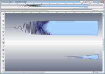 10 Unshielded -6dB - wave.png42.6 KB · Views: 100
 -
 9 Shielded -6dB - wave.png42.1 KB · Views: 99
 -
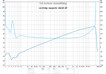 8 Unshielded response -6dB.png146 KB · Views: 94
 -
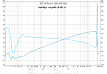 7 Shielded response -6dB.png157 KB · Views: 98
 -
 6.JPG918.4 KB · Views: 100
 -
 1 Demian's suggestion.PNG124.7 KB · Views: 150
 -
 4.JPG965.3 KB · Views: 101
 -
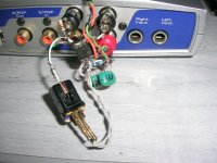
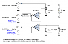 3 Schematics of actively buffered freq response measuring jig.PNG24.2 KB · Views: 151
 -
 5.JPG965.6 KB · Views: 97
I've built some 50 ohm attenuators, 20dB and 40dB. They look pretty good into the low MegaHertz. OPA2604 are 10nV/Rt Hz. Maybe this will get done this afternoon as it's snowing pretty good at the moment.
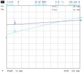
The HP 3577 uses a 8/12 bit successive approximation ADC and a pre-scaling VGA which takes two passes at each data point. the 10Hz bandwidth requires 370ms to settle, so each step is set for 2 seconds, and averages set to 32 and "A" Attenuator at 0dB. Press the trigger and go pour another cup of coffee.
Phase across the Caddock 5k resistor seems pretty much the same at 3kHz, around +1.01 degree.
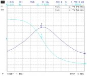
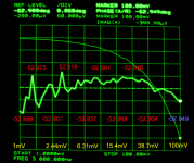
So that you can see what we're dealing with -- a plot of phase vs generator level from 1mV to 100mV, courtesy of the 5K caddock and AT cart.
The HP 3577 uses a 8/12 bit successive approximation ADC and a pre-scaling VGA which takes two passes at each data point. the 10Hz bandwidth requires 370ms to settle, so each step is set for 2 seconds, and averages set to 32 and "A" Attenuator at 0dB. Press the trigger and go pour another cup of coffee.
Phase across the Caddock 5k resistor seems pretty much the same at 3kHz, around +1.01 degree.
So that you can see what we're dealing with -- a plot of phase vs generator level from 1mV to 100mV, courtesy of the 5K caddock and AT cart.
Attachments
I haven’t tested this.
?
George, the open circuit voltage means there is no path for current in the coil, flux change will induce an open circuit voltage just as it will induce a closed circuit current and anything in between. I just wanted to prove to myself that nothing funny happens. So nothing changes same RIAA pre-amp just one with "infinte" input impedance and that means attached directly to the cart.
What Demian suggested is an actual electrical flux coupling, I don't think (which my sims indicate) that this mimics the flux ring (MI) or moving magnets (MM) wiggling on the cantilever i.e. no mechanical impedance elements.
Last edited:
it seems there would be several coupled systems to model for this. The stylys groove interaction, the cantilever stiffness and internal resonance, the compliance and resonance of the pivot, the interaction of the magnet and the fixed magnetic circuit or vice versa depending on which moves(which could be quite strong), and the magnetic to electrical conversion. What i proposed only looked at the last part.
Maybe building an accelerometer setup to drive the system may be necessary to untangle all of this. Something like this: COLUMBIA ACCELEROMETER 400P w/ Case | eBay would work. Not sure how much voltage is needed to drive it.
Maybe building an accelerometer setup to drive the system may be necessary to untangle all of this. Something like this: COLUMBIA ACCELEROMETER 400P w/ Case | eBay would work. Not sure how much voltage is needed to drive it.
epid=1654685801&hash=item3f66d3dd24:g:NOMAAOSw7XZXiCSy:rk:51😛f:0]COLUMBIA ACCELEROMETER 400P w/ Case | eBay[/url] would work. Not sure how much voltage is needed to drive it.
You need to be careful some of the best quartz accelerometers have built it pre-amps and are not reciprocal.
I added a weakly coupled flux to the coil as the stimulus and as expected I got the constant velocity response out since a SPICE source is constant amplitude
Scott, in the sim did you get what I got from measurements (attachments 7,8 in post #425)?
it seems there would be several coupled systems to model for this.
Demian, I only wish there will appear someone who will provide evidence of just only weak reciprocity.
I have found none and I have given up trying to search any more.
George
Decades ago I had a grad student to the following calculation. I wanted to address the "loading needed to damp the stylus" stuff. Personally, then, I thought loading did nothing positive for a cartridge and the calculations supported that thought.
A straightforward calculation could be the starting point- take the compliance of the cartridge (dynes/???) as the input energy and the voltage across a 50K resistor as the output. As I remember the loss path is 120 dB or some such in power. The energy in to the coils to produce a measurable result out would probably melt the housing first.
In many cartridges the magnetic path would not be particularly good as a motor. In some it would never work.
Jack,I've built some 50 ohm attenuators, 20dB and 40dB. They look pretty good into the low MegaHertz. OPA2604 are 10nV/Rt Hz. Maybe this will get done this afternoon as it's snowing pretty good at the moment.
The HP 3577 uses a 8/12 bit successive approximation ADC and a pre-scaling VGA which takes two passes at each data point. the 10Hz bandwidth requires 370ms to settle, so each step is set for 2 seconds, and averages set to 32 and "A" Attenuator at 0dB. Press the trigger and go pour another cup of coffee.
Phase across the Caddock 5k resistor seems pretty much the same at 3kHz, around +1.01 degree.
So that you can see what we're dealing with -- a plot of phase vs generator level from 1mV to 100mV, courtesy of the 5K caddock and AT cart.
Sorry for my ignorance, but what exactly are we seeing, I can't figure it out no matter how hard I try.
1) You refer to a 5 K attenuation resistor, but when I look at the marker in your image at 100mV it says Imag(A) -399,9 uV. This is at the low voltage end of the cart at input A ? in that case no 40dB dB attenuator has been used, and almost 50mV is over the cart, true ? Or did you already use an 40dB Amp before the A input ??
2) you planted a number of figures on the image in red and blue, seemingly the Phase (A/R), but how can it be so accurate. ? And 52 degrees seems quite suspect at 3Khz ? In your previous image in #385 it was over 85 degrees below 10Khz.
3) What do the two lines represent in the figure, the smooth one going from top left to bottom right and the wobbly line in the middle.
I suspect the wobbly line represents Imag(A), in that case it is still a voltage, with a scale of 50uV/div, correct ? And how does this translate into a 0.46mH inductance L.
Hans
As I remember the loss path is 120 dB or some such in power. The energy in to the coils to produce a measurable result out would probably melt the housing first.
I cant comment on the robustness of the housing but I will gladly agree that the loss is higher that 90dB
George
You need to be careful some of the best quartz accelerometers have built it pre-amps and are not reciprocal.
True, but the vintage tiny ones needed for this won't have a preamp. Here is more: https://www.bksv.com/media/doc/TechnicalReview1976-2.pdf
True, but the vintage tiny ones needed for this won't have a preamp. Here is more: https://www.bksv.com/media/doc/TechnicalReview1976-2.pdf
Not necessarily true I have one I got from Kistler 30yr. ago and they were very proud of it, it even came with traceable calibration. I used it to demonstrate speaker damping (probably no one was paying attention).
Scott, in the sim did you get what I got from measurements (attachments 7,8 in post #425)?
Demian, I only wish there will appear someone who will provide evidence of just only weak reciprocity.
I have found none and I have given up trying to search any more.
George
George, what I'm doing is different maybe I can elaborate if I could generate some pictures later.
Just look and the reciprocity theorem (I think there is a nice AES paper from the 40's). Loss is not permitted be it thermal dissipation or radiation. The loss in the damping material and coupling to the headshell/arm is large compared to the power delivered to the load. Play an LP with the volume at 0 and "listen" to the mechanical system, this is all lost energy.
Yup I've done such calcs using published cart mechanical impedance figures from back in the day, and IIRC there's 5 or so orders of magnitude in it. It doesn't happen. But, there's no slaying this dragon...………The loss in the damping material and coupling to the headshell/arm is large compared to the power delivered to the load.
LD
Last edited:
Slightly off topic, but of interest. Chatting with Wayne Kirkwood about some stuff and he mentioned that he had done some testing with short cable and no additional capacitance on a stanton cartridge and found that, at very low capacitance (20-30pF total) you get a lot of high frequency distortion. Add C and it gets damped out. 47K resistive load.
On fact value this does not make any sense at all unless there is some mechanical resonance that is out of phase with the electrical resonance and somehome magically cancels. If so I need to wake up the mechanical resonance thread!
On fact value this does not make any sense at all unless there is some mechanical resonance that is out of phase with the electrical resonance and somehome magically cancels. If so I need to wake up the mechanical resonance thread!
On fact value this does not make any sense at all unless there is some mechanical resonance that is out of phase with the electrical resonance and somehome magically cancels. If so I need to wake up the mechanical resonance thread!
Could be overloading the pre-amp with HF IM components beyond audio because the unloaded Q is very high. I have been simulating some experiments with a zobel network to kill the Q. I still have my 500-50k sweep and will try and see.
I'd stick with Occam's razor until proven otherwise. Come to think of it, "C" adding damping makes no sense.
Last edited:
I you remove all C you just get a first order L-R response? Am I being fick again?
mind you this Phono Cartridge Loading For Moving Magnet? - Graham Slee Audio Forum | HiFi System Components - Page 1 as presented makes even less.
mind you this Phono Cartridge Loading For Moving Magnet? - Graham Slee Audio Forum | HiFi System Components - Page 1 as presented makes even less.
- Status
- Not open for further replies.
- Home
- Source & Line
- Analogue Source
- Cartridge dynamic behaviour