I you remove all C you just get a first order L-R response? Am I being fick again?
mind you this Phono Cartridge Loading For Moving Magnet? - Graham Slee Audio Forum | HiFi System Components - Page 1 as presented makes even less.
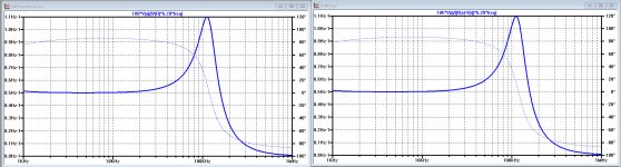
Self resonance as in Jack's plot has a very large Q beyond audio.
would that cause audible nasties though?
It could if it caused IM due to high level mis-tracking, etc. that is outside the audio BW, me thinks?
No but it t means you could pick up Rugby time code and display it in the preampwould that cause audible nasties though?
😉 In the UK there's a timecode broadcast nationally on a 60kHz carrier or at least there was......
A slightly more serious answer is it depends on what else is about up there at resonance and how the preamp copes trying to amplify it.
Probably not though given the coils are screened.......
LD
Instead of doing a series-through impedance measurement, what if you used a return loss bridge? The 3577 bridge only goes down to 100kHz, but the HP E5090A does DC to 2GHz.
I have the 5090 and an E5100A VNA (10kHz-180MHz), but I have no MM carts to test. I did a couple of quick tests on a MC; Self Fres of ~2.78MHz (drive level was -30dBm or 7mV).
If someone would send me a MM cart, I would be glad to test and post the results.
I guess if one were only interested in the audio range you could use two microphone transformers to make a directional coupler.
But if the cantilever resonance or one of its modes is up there then the prospect of IM in the preamp arises I suppose.No but it t means you could pick up Rugby time code and display it in the preamp
😉 In the UK there's a timecode broadcast nationally on a 60kHz carrier or at least there was......
A slightly more serious answer is it depends on what else is about up there at resonance and how the preamp copes trying to amplify it.
Probably not though given the coils are screened.......
LD
LD
The B&K link I posted has a number of measurements that may shed some light on response and resonances.
The B&K link I posted has a number of measurements that may shed some light on response and resonances.
Interesting article, also clearly showing the importance of a low tip mass.
Hans
After some experiments with the REW impedance jig, which found that my soundcard was lower impedance than specced and had 10nF input capacitance,
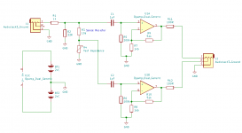
I am assembling a revised jig as attached.
I am attenuating the souncard output by 30 dB and then amplifying the sense voltages by 30dB to get a usable SNR at mV levels.
I am assembling a revised jig as attached.
I am attenuating the souncard output by 30 dB and then amplifying the sense voltages by 30dB to get a usable SNR at mV levels.
Attachments
Hi David,After some experiments with the REW impedance jig, which found that my soundcard was lower impedance than specced and had 10nF input capacitance,
I am assembling a revised jig as attached.
I am attenuating the souncard output by 30 dB and then amplifying the sense voltages by 30dB to get a usable SNR at mV levels.
I made some calculations and rearranged your design a bit, enabling the lowest possible measuring limit over the Cart, in this case 58uV when using a 10Hz BP filter.
To make such a low uV measurement possible, 10Hz BP filters should be used in the digital domain to reduce the noise , thus increasing the S/N.
To make a measurement relatively accurate, a SNR of 35dB should be aimed for as a minimum.This will give a max phase error of 1 degree and a max magnitude error of 0,1dB.
A resistor in series with the Cart should be used that has very little effect on the phase error, too low and the signal will become weaker as needed, too high and the phase relation becomes highly inaccurate.
An optimum seems 100 Ohm, giving a phase error of 0,5 degrees at 3kHz, the preferred frequency to be used for measuring, yet producing only 1.4nV/rtHz or below 4.5nV noise for a 10Hz window.
Using an A/D convertor with a Sampling rate of 192Khz having an estimated noise at -100dB, will produce 0.1uV noise through a 10Hz BP filter.
The noise from the OPA at low output R should be a bit above this level, so I’ve set it at 1uV to be on the safe side.
A 5534A produces 3.5nV/rtHz, or 11nV in a 10Hz window.
Therefore to get the calculated 1uV at output R, the amp should have a Gain of 100. Noise from the 5534A added with the 100 Ohm termination resistor gives 1.2uV noise at the output of a 10Hz filter.
To get the 35dB SNR, signal at output R (see circuit diagram below) should now be ca 68uV@3kHz.
For the given Cart, the VM540ML, this translates into 58uV at the input of the Cart. With the shown voltage divider 5k6/33 a 10mVrms@3Khz must be used as input signal.
This 58uV@3Khz is also the voltage over the cart, thus being the low end limit of the measurement.
The complete circuit diagram is given below.
Since LTspice has a huge dynamic range, the calculation is made both before (in red) and after (in blue) the OPA’s as a prove that the result is identical and that the Phase errors introduced by the OPA’s are cancelled by using two identical amp’s.
At the same time when comparing the two, shows that the transfer of the original circuit diagram is not accurate in phase and magnitude, thus not suited to use for the envisaged purpose.
Hans
Attachments

First measurements
REW has a feature that the sense resistor cannot exceed 10k and the graphed impedance cannot exceed 10k
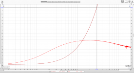
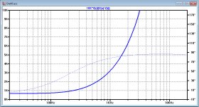
The G1042 measures 660R +500mH at low frequencies.
Phase reaches 45 degrees at 200Hz
At 1kHz the resistance has increased to 850R
At 2KHz the resistance has increased to 1k4 and phase peaks at 77 degrees
Graph is unchanged over 50dB dynamic range
REW has a feature that the sense resistor cannot exceed 10k and the graphed impedance cannot exceed 10k
The G1042 measures 660R +500mH at low frequencies.
Phase reaches 45 degrees at 200Hz
At 1kHz the resistance has increased to 850R
At 2KHz the resistance has increased to 1k4 and phase peaks at 77 degrees
Graph is unchanged over 50dB dynamic range
Attachments
Last edited:
I tried measuring a 8k2 resistor and the phase was flat at zero all the way to 20kHz
Last edited:
Core losses could explain the resistive part increase. Is it a coincidence that the phase falling above 2kHz is the lower end of the standard MM cartridge suck out
Hi David
Electrically, your cart is close to the AT110E.
Your impedance measurement is very close to what I have measured on the AT
Cartridge dynamic behaviour
In all these tests I am connecting (hardwired and in sims) the external source in series with the cartridge for more than ten years.
I scratch my head if it is time to connect the external source in parallel with the cartridge.
George
Attachments
If you are going to put it in parallel shouldn't you drive it with a current source instead of a voltage source? A voltage source has no resistance, it is a short circuit.
Sorry David,
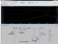
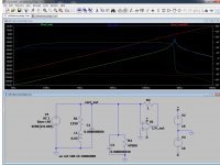
I made a mistake in my display in #451.
Since you have the 10K resistor at the other side of the Cart, I switched V(a) for V(r) in your case, now both being exactly the same in phase and magnitude.
Here is the corrected version for the two designs.
But still completely valid is the noise calculation to go as deep as 58uV over the cart.
Hans
Attachments
I plan to improve my jig tomorrow. I will ac couple the input and remove the 1uf & 100k at the opamp inputs - the 100k is in parallel with the test sample.
I am working down to -80dBfs when allowing for the 30dB gain so no sign of the low level inductance fall
I am working down to -80dBfs when allowing for the 30dB gain so no sign of the low level inductance fall
- Status
- Not open for further replies.
- Home
- Source & Line
- Analogue Source
- Cartridge dynamic behaviour