The transformer is a 30-0-30 one. Mine was blown when I bought the amp, but it is working fine now that i have replaced it (about three years ago). Still using it instead of a soundbar on the TV. One word of warning - turn on the amp before the source, or the fuse sometimes blows.
Barry
Barry
That is 30-0-30 VAC for a 25W amplifier.
This checks with the parts list for a service manual available from Hifi Engine for the version using the TDA1514 where the schematic shows +/- 28Vdc supply rails.
The datasheet for TDA1514A presumably an update shows a maximum supply rail voltage of +/-30Vdc. While that rating may be conservative on the part of Phillips the makers, apparently not so much in the Cambridge application.
Last edited:
I think the rectified DC voltages at rated load with a single bridge rectifier are more like +/-41VDC for a 30-0-30VAC transformer. For +/- 28DC, the transformer would likely be a 20-0-20VAC type.
Those older TDA chips had a terrible reputation for failure in mains powered applications so its likely that the problem was poor choices of transformer.
Those older TDA chips had a terrible reputation for failure in mains powered applications so its likely that the problem was poor choices of transformer.
You just made me go back to check that
Didn't I say that the transformer for the MK2 was 2x20V 120VA (A1 MK2 is the one with 2 TDA1514A chips)
This thread is going nowhere and anybody can have a working one of ebay for 50/60 quid so basically not worth repairing
Didn't I say that the transformer for the MK2 was 2x20V 120VA (A1 MK2 is the one with 2 TDA1514A chips)
This thread is going nowhere and anybody can have a working one of ebay for 50/60 quid so basically not worth repairing
The transformer is a 30-0-30 one. Mine was blown when I bought the amp, but it is working fine now that i have replaced it (about three years ago). Still using it instead of a soundbar on the TV. One word of warning - turn on the amp before the source, or the fuse sometimes blows.
Barry
In the light of the comments by RS232 about transformer specs can you clarify if your repair is for the mk1 in question and whether or not your 30-0-30 means rectified voltage or secondary ac volts.
I would suggest a 160VA transformer in the 20x2 or 22x2 max to get a rail voltage around the 28/30 volts DC but again it's just a suggestion because I don't think is worth the price of a new transformer.
From the size of the output devices I would probably put an 18-0-18 (or rather 2x18VAC wired as above) transformer to get 25V DC secondaries. Any more than that would be pushing it. I'd probably go for 120VA
the only label i could find on this transformer was this 230V other than that i could find anything on the labels.
redone this test just to make sure and it still shows open circuit.
i am in the uk. i could really appreciate it if i could have it!!! 😱
is there a way i can make sure that it was the thermal fuse inside the transformer or is that something risky to do.
if people would like design of the bottom of the pcb then i can send pictures or even possibly make a schematic on a program.
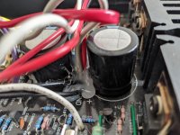
Can you post an image of the bottom of the board with all the hot melt glue covering the transformer secondary winding.
You need quite a lot of heat to solder a length of copper in the primary winding because this gets conducted away from the heat source.
The amplifier is now 25 years old which raises the question of cold solder joints which is not an uncommon problem over time. There is a certain amount of heating involved with electrical currents.
It will cost you nothing to remove the old solder and remake the joints then retest for continuity in the primary winding.
Last edited:
So i have someone who said they have a spare transformer which they can give. I will wait on that and then get back to you guys.
I will get pictures of the bottom of board tomorrow!
I will get pictures of the bottom of board tomorrow!
Going to buy one just to get to the bottom if it
Just found one with a faulty channel going to make him an offer
PS: just bought it 30 quid + postage
Just found one with a faulty channel going to make him an offer
PS: just bought it 30 quid + postage
Last edited:
Can you post an image of the bottom of the board with all the hot melt glue covering the transformer secondary winding.
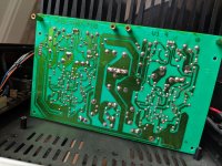
Here is the image of the bottom of the board and a image of the hot glue.
Attachments
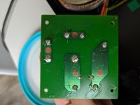
Nothing there, no signs of any overheating. Can you photo the bottom of the board connecting the mains to the transformer primary via the fuse.
Im not sure if this is the board you asking about but i think this is the right one. If this isn't could you elaborate.
Yes and the solder does not look too good. I suggest you remove this and remake all connections with fresh solder. Then retest for continuity.
You will need plenty of heat in your iron for the primary winding as the copper in the transformer is a good conductor of heat. You are not going to suck all the solder off in one step.
A small wire brush would be useful to clean the ends before the continuity test or subsequent application of fresh solder if there is a positive result.
Amplifier arrived today and is not working but...
I measure 49V AC from side to side or if you prefer without centre tab witch gives about 24V x 2 and transformer is 120VA tops
I measure 49V AC from side to side or if you prefer without centre tab witch gives about 24V x 2 and transformer is 120VA tops
Left channel fried both power transistors shorted (parts ordered)
Had a look around and found two added resistors on the CD input by the RCA sockets (removed I like things original)
transformer unloaded reads +/-24.5Vac on both supplies (24x2Vac)
Didn't remember this model been so well made, build quality is decent for this type of amp
and on top of that this came with a bonus MM card and I think I'm keeping this one
- Home
- Amplifiers
- Solid State
- Cambridge audio a1 mk1 not powering on.