The glue is the least of your worries. That will just pull off cleanly with pliers/cutters. Manufacturers love that stuff for some reason.
We would need to know the correct voltage for any replacement transformer and that really needs a circuit diagram.
We can estimate... if you look at those two large black capacitors they will have a voltage rating on them. For example 6800uF (the capacitance) and say 50V DC (the maximum working voltage).
That DC voltage sets an absolute upper limit and so working back we could say that 50 divided by 1.414 (the magic number for all these calculations) gives 35 volts.
So a transformer would have to be no higher than 35-0-35 volts AC. In practice it would more like be a 28-0-28 type which in my example would give 40 volts across each of those capacitors BUT ideally we need to know for sure what the manufacturer used.
The other big question is whether the transformer has failed on its own or was it pushed... meaning there is some other problem lurking there that has damaged it.
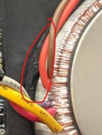
In the picture there is 'something' near those wires. What is it?
I'll look in again later 🙂
We would need to know the correct voltage for any replacement transformer and that really needs a circuit diagram.
We can estimate... if you look at those two large black capacitors they will have a voltage rating on them. For example 6800uF (the capacitance) and say 50V DC (the maximum working voltage).
That DC voltage sets an absolute upper limit and so working back we could say that 50 divided by 1.414 (the magic number for all these calculations) gives 35 volts.
So a transformer would have to be no higher than 35-0-35 volts AC. In practice it would more like be a 28-0-28 type which in my example would give 40 volts across each of those capacitors BUT ideally we need to know for sure what the manufacturer used.
The other big question is whether the transformer has failed on its own or was it pushed... meaning there is some other problem lurking there that has damaged it.
In the picture there is 'something' near those wires. What is it?
I'll look in again later 🙂
Attachments
Without re-reading all of these cumbersome descriptions
let me say that a transformer failure is unlikely.
In post 1 the OP reported that a fuse was blown, but did
not care to state clearly which one of five. "Main" fuse may
mean mains fuse ? All this help will be useless if basic
communication fails.
let me say that a transformer failure is unlikely.
In post 1 the OP reported that a fuse was blown, but did
not care to state clearly which one of five. "Main" fuse may
mean mains fuse ? All this help will be useless if basic
communication fails.
In the picture there is 'something' near those wires. What is it?
Rubber suspension
Between themselves, you need to check a) two thinner wires (mains winding), b) three wires going to the PCB of the amplifier.
The fuse which had blown was the one closest to the heat sink on the main board. I did say the value but if you don't have the amp or schematic then i agree hard to tell.
On the transformer it says that it is 230V and the thing you pointed out on the transformer is just a label on the transformer.
On the transformer it says that it is 230V and the thing you pointed out on the transformer is just a label on the transformer.
Between themselves, you need to check a) two thinner wires (mains winding), b) three wires going to the PCB of the amplifier.
Could you expand by telling me colours of the wires i should be checking?
The fuse which had blown was the one closest to the heat sink on the main board. I did say the value but if you don't have the amp or schematic then i agree hard to tell.
There are two fuses close to the heat sink.
These are respective channel output fuses.
This has nothing to do with transformer operation.
Without re-reading everything: is the amp
powering up in some way (LED) ?
However I am not sure why anybody would
want to assist with an amp fix, working with
mains voltage, where apparently basic know-
ledge about repair procedures and testing
strategies is missing.
You are looking at the wrong fuses. If you look at the 2 capacitor and then look slightly up there is a fuse. It is kinda behind a white wire. Thats the fuse i am talking about.
There is no led showing when the amp is plugged in and on.
There is no led showing when the amp is plugged in and on.
Last edited:
In other words there are four fuses on the main board
and two of them closer to the heat sink - as I said. These
two have nothing to do with transformer operation and
LED will normally light up even if they are missing.
Not sure you checked for conductivity of the mains circuit
properly using the ohmmeter (reading "1" means overflow,
i. e. infinite resistance, probes not put together, open circuit,
otherwise reading should be different from "1" if the "range"
setting of the meter is correct/adequate).
Apart from primary open winding of the transformer you may
want to investigate the power switch :
- pull the mains plug form mains
- remove the power switch insulating sleeve
- check for resistance using the ohmmeter
- if not sure send a picture.
If you find the switch to be operative, a thermo fuse may have
failed inside the transformer. In this case your local transformer
winder can help. This may have happened during a party overload
I suppose you checked the mains fuse ..
Without re-reading all of these cumbersome descriptions
let me say that a transformer failure is unlikely.
In post 1 the OP reported that a fuse was blown, but did
not care to state clearly which one of five. "Main" fuse may
mean mains fuse ? All this help will be useless if basic
communication fails.
I agree with the comment 'unlikely' on the failure of a toroid but you really should read it all 🙂
We have established that there appears to be an open circuit as measured directly between the two primary leads into the transformer. See image in post #17.
We have also proved the meter at least reads 0.00 when the leads are shorted together.
Rubber suspension
Could be. I was curious because it looks like there is some lettering on it (unless a reflection) and so I wondered if it could be heat-shrink hiding something within 🙂
I bought one of these for £5 off ebay.co.uk and repaired it. Its a Mike Creek design and sound good enough (its in my workshop).
The main suspect in these are the TDA1514A - they fail a lot causing a fuse blow. Especially if they failed and someone replaced them with new production TDA1514A which are about 100% fakes and blow anytime. Marshall used the same in some of their amps and users who got new production ones (not Philips) reported fireworks on start up.
If i was you, I would first check these to verify that they`re ok and would then look for the problem. Disconnecting the transformer and measuring voltage would give you a hint if ok or not but unlikely dead. Diodes in these are pretty high rated. Indeed, the amp may power up but blow a fuse so fast you don`t see it on. I would replace all caps in the PS first.
M. , I think I gave useful instructions in 27 and 29 without need to read everything
again, especially when it goes into calculations for a new transformer etc. Basic
knowledge and first efficient tests first, I think. He did not confirm that the glue was
scraped off to get at the primaries and if it is open there my comment in 29 applies ..
It may be easy to lift the small board in order to get at the primary brown/orange wires.
Last edited:
The main suspect in these are the TDA1514A
Where would a TDA1514A IC be located in the amp of post 5 ? Thanks.
I believe that pic shows two plastic power transistors and a Vbe multiplier transistor mounted on each heatsink rather than the PCB mounting style TDA 1514A IC. An IC version most likely would be Cambridge's own, later versions design. Look closely at the right edge of the heatsinks and note the mounting bolts and metal flanges of (probably) TO218 type transistors.
Already post 35 yet nobody demanded a change of caps.
Something is really going wrong here.
But wait, perhaps I should read again ..
Something is really going wrong here.
But wait, perhaps I should read again ..
No need to. The primary issue is that there appears to be no transformer output. The capacitors, if indeed they are so bad as to urgently need replacement, can still wait until the transformer condition is certain. If the transformer is toast, you're wasting time and money fiddling about with what follows.but wait, perhaps I should read the thread again ..
The OP is obviously unfamiliar with power amplifier electronics - perhaps fault tracing and repairs are also beyond his understanding and capability but that's hardly a reason to remonstrate about how the thread isn't progressing.
I have read through the posts however im kinda busy but will get back to guys in a day or two!
I dont have the greatest amount of knowledge when it comes to amps however nothing wrong with trying to fix.
I dont have the greatest amount of knowledge when it comes to amps however nothing wrong with trying to fix.
🙂 No problem.
The important thing at this time is for you to be 100% certain whether or not that transformer is open circuit... and if it is then you have to be realistic as to what is possible, particularly considering that there may possibly be a problem within the amp circuitry itself that would have caused the failure in the first place.
The important thing at this time is for you to be 100% certain whether or not that transformer is open circuit... and if it is then you have to be realistic as to what is possible, particularly considering that there may possibly be a problem within the amp circuitry itself that would have caused the failure in the first place.
Remove the fuses on the amp board and power up see if you have any AC voltage on the fuse holders had an A1 that the thermal fuse in the transformer went open.
There are several different variants of the "Cambridge Audio A1". The first is this one - designed by Mike Creek and a transistor output based design. Three others I know of are chip amp based - so the comment about the TDA1541A does not apply here.
I expect the transformer will be close to 25-0-25VAC at 100VA.
I expect the transformer will be close to 25-0-25VAC at 100VA.
- Home
- Amplifiers
- Solid State
- Cambridge audio a1 mk1 not powering on.