I can probably handle a cnc batch of "golden heart" type shielding to hand out. So it's shielded and decoupled physically from the board itself, on it's standalone board.
this glock looks like balls ! and eventually lock !
Sorry my french : I have no doubt we reclock before the attenuator, but what I asked was if it is worthing with all the good USB/Spidf module with SDKA clock ?
Or you need it the MCLK to inject it on the atenuztor flip flop CP pin ?
The Mclk is only working if we can slave the USB with it, no ? But the cpld of those boards re inject its 2 pS jitter towards the flip flop anyway ?
I have found the Crystek 957 to sound good with 1 uF ECU or acrylic from CDE. It is partialy shielded. (and yes I know there are MLCC class 2 inside but the 1 uF at the feet improves breatly the sound I have found)
Last edited:

Schematics containing copyrights are up again as the author posted them in this thread:
- https://www.diyaudio.com/community/...ate-nos-dac-using-tda1541a.79452/post-2384742

Schematics containing copyrights are up again as the author posted them in this thread:
- https://www.diyaudio.com/community/...ate-nos-dac-using-tda1541a.79452/post-2384742
Thank you!
Sorry my french : I have no doubt we reclock before the attenuator, but what I asked was if it is worthing with all the good USB/Spidf module with SDKA clock ?
Clocks etc vary.
Or you need it the MCLK to inject it on the atenuztor flip flop CP pin ?
If we make our own clock, we know what it is like.
The Mclk is only working if we can slave the USB with it, no ?
Yes. For SPDIF we can use ASYNC reclock.
But the cpld of those boards re inject its 2 pS jitter towards the flip flop anyway ?
We reclock on the TDA1541 board, so only those flip flops and the clock itself matters, if we keep everything on board.
I have found the Crystek 957 to sound good with 1 uF ECU or acrylic from CDE. It is partialy shielded. (and yes I know there are MLCC class 2 inside but the 1 uF at the feet improves breatly the sound I have found)
It is a pretty low end clock. I like John's differential clock better.
Thor
I would keep the SMA/uf-L mclk inputs near the embeded MCLK anyway for those having high end clocks (Andrea Mori's, Pulsar Clock, ...) in order to give choice.
Damit the clock dimension rise the pcb in one direction, beginns to looks like a french baguette !
Damit the clock dimension rise the pcb in one direction, beginns to looks like a french baguette !
Schematics containing copyrights are up again as the author posted them in this thread:
- https://www.diyaudio.com/community/...ate-nos-dac-using-tda1541a.79452/post-2384742
If one is using it or any published shematic in a diy project GB for PCBs, it would be fair to ask a gentlemen agreement to him as an authorisation anyway, but if at the end the schematic is not the same. Concepts (ideas : for illustration : "Class A") can not be copyrigthed, rigth ?
Kudos yes we should cherish life experiences, simplicity at times can bring lots of meaningTable each 'leg' sitting in water bowl. Sambal, sambal and more sambal. Ichan Bilis, ochre, kangkong, small fresh water fish about width of palm which had unusually disproportionate size heads - were 'dried' with salt, and for some reason with maggots (left to roam free before preparation). Fresh water (pond) 'snapper' (Nangai?) fed Tapioca leaves. Caught with net and thumb through the 'eye' to 'kill'.
Wear feet covering, the worms will 'up through your skin'.
Walk down jalan kampung, my wife at the time with scissors and basket, philosophy = 'take what you need, it all grows'. I was the only 'orang putih', and I could have stayed there happily. Treks, waterfalls, dragon fly the size of tennis ball. Rivers. Huts. Long-houses.
Slippery when wet tiles, sharp edges, big barrels full of water for 'wash' and toilet 'flush', squat ceramics for the same and ... reverse cycle air con and internet flat screen TV inside the house 🙂
I know how to grow a pineapple plant - you cut the top off and stick it in the ground. She would carve the pineapple from its skin, you'd have to see it to believe the consistency and the 'lack of waste'.
Looking back, I cherish it. Share, not for ego so much (there is some), but with my life 'as boring as it is' - to shout "I did exist !!!!!" 🙂
Thank you very much Khun Thorsten.Not really "Optimum" but rather minimum value to guarantee certain results under worst case conditions.
Another way. After looking carefully I decided that this is a bit too much dependent on parameters we cannot sufficiently control in the real world and long term, to recommend it.
Using very large capacitance values means capacitors need selecting for < 1/2 LSB current leakage under all possible operating conditions (temperature winter vs summer etc) and long term stable.
If this is done, we can afford to lower FDEM to values where the DEM ripple is at very low frequencies.
It means that the frequency (FDEM) with which the ~ 20nS glitches on the DEM Filter pins occur is much reduced over (say) 176.4khz.
At the same time the ability of the capacitors used to sink these glitches and avoid them entering the audio path is reduced.
So I expect that there will be subtle sonic differences.
But honestly I have no trust in the long term, stability of electrochemical condensers. 1Month? Sure. 1 Year, likely. 10 Years, yeah not happening.
Now C0G Ceramic or SMD Film condensers will still be 100% on spec in 10 years after much worse abuse the the electrochemical condensers.
So I decided against low frequency DEM after extensive consideration and instead prefer to focus on minimising problems from using 4 X FS DEM.
Speaking of Focus....
Thor
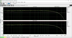
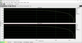
Proof of sinc roll-off. sin(x)/x causes about -3 dB drop at 20 kHz.
3.2dB in theory.
I will try Thor's compensation network.
I didn't really design anything for Op-Amp I/U conversion.
You can use a peaking lowpass at 22.05khz with a Q ~ 1.1. Best do "curve fitting" using trial/error, at 22.05khz the roll off theoretically is 3.9dB.
You can start here:
3rd order Sallen-Key Low-pass Filter Design Tool
The 1.8R/2.2uF simulate 1.8k I/U resistance at the O-Amp with 2.2nF parallel capacitor, to create the same lowpass, without affecting a second stage SK filter.
This gives ~ 3.4dB @ 20khz so it might slightly overcompensate. Adjust C2 for starters to get the flattest response. May need to adjust all R&C, but start with C2 and perhaps both resistors equally.
Thor
Btw, totally off topic but I wondered : Many people here if I am not wrong filter current output of DAC chip (glitches) with different technic like coil or low pass.
I am not asking for the specific TDA1541A we talk here but for all the DAC current output ics ?
If please some noticed substantial improvments here, please tell. Ii know some guys like @abraxalito uses it and has kit.
I am not asking for the specific TDA1541A we talk here but for all the DAC current output ics ?
If please some noticed substantial improvments here, please tell. Ii know some guys like @abraxalito uses it and has kit.
Btw, totally off topic but I wondered : Many people here if I am not wrong filter current output of DAC chip (glitches) with different technic like coil or low pass.
No. I think you misunderstand what is going on.
Any DAC needs a lowpass filter. Current output, Voltage output.
Some modern "SOC" integrate everything on chip.
Here in the context we are talking about using a filter with a peaking response to compensate HF rolloff non-oversampling DAC's show.
If please some noticed substantial improvments here, please tell. Ii know some guys like @abraxalito uses it and has kit.
No, no magic bullet here, sorry.
That said, done right passive LC filtering works well and there is no question "which is the best Op-Amp for the filter", instead it is "which is the best choke and capacitor"
Thor
Hi, Thanks. I wasn't talking related to the conversation before or about the output filter after I/V (reconstruction and low pass filter because aliasing).
But what happens at the output of the DAC before any I/V. Some say there are glitches spikes which should be tammed before any I/V.
Or do you mean in your answer than anyway it is handled also by the post I/V filter ? (and so the coil and cap values & quality matter).
Damit I want to glock anything !😊
The DAC chip will have some finite time to settle the output. This is a kind of a HF noise. But, with passive filter, is not a problem. And, the slew rate attenuation before the TDA1541 will tame/reduces the substrate leakage that will add to the settling time (and all the time).
And, the very own process of changing output produces a "glitch" in the output, since it changes in <1µs the information/level (if are zero filter in the DAC out). Hence the "staircase" for a zero filter DAC out. The staircase slew rate is far higher in frequency than even the 192kHz sample rate.
Some old chips are more spiky than the TDA1541 for the settling issue AFAIK.
A direct connected ampop like traditional active I/V converter will be most sensitive to it, as we know, and needs to be really well chosen.
If I understood well the very question.
Very short answer, but I think is something in these lines... if I not missed something (perhaps I'm oversimplified)... and I'm not very didactic unfortunately to explain things...
.. as in the higher order filters that Abraxalito is using, similar to what Zanden did with all those inductors in their 1541A DAC?Hi, Thanks. I wasn't talking related to the conversation before or about the output filter after I/V (reconstruction and low pass filter because aliasing).
But what happens at the output of the DAC before any I/V. Some say there are glitches spikes which should be tammed before any I/V.
😊
IIRC it showed a smoother waveform with less 'steps' which is perhaps what you meant by 'glitches' ?.
Last edited:
Hence the "staircase" for a zero filter DAC out.
They are also there in a DAC with filter, just much smaller steps. Imagine the filter as an interpolator that takesa few dozend to a few 100 (or more in some cases) data points in 16/44.1 and then recreates a new waveform that does not reliably pass through the original data points but is (say) 24/352.8kHz.
The staircase slew rate is far higher in frequency than even the 192kHz sample rate.
Any DAC that does not integrate the filter on chip will have high dV/dT or dI/dT steps at the output.
These are just the "intentional" behaviour.
Non-Intentional behaviour of the switching systems in the DAC (IC) may give rise to additional issues. A big issue for CMOS IC's is charge injection via gate capacitance. Bipolar IC's have their own problems.
The best way to suppress the unintentional glitches as well as of slowing down the edge rate of the intentional signal, is to add a suitable low inductance capacitor directly on the DAC output (not if using CFB Op-Amp's as I/U converter).
This can also help to make decompensated Op-Amp's (which sadly get rare) stable, these Op-Amp's are more suited to I/U conversion duty as they typically have a wider GBWP and higher slew rate than unity gain stable Op-Amp's. We could even take Op-Amp's with accessible compensation node's and use extra "feed forward" decompensation to boost slew rate even more. |
The LM318 (as used in the MF Digilog by TdP) is such an IC. We can easily boost it well past 200V/uS if we use 10nF from input to GND and the classic 1.8k//2.2nF I/U conversion. The 10nV/|/Hz is on the high side but will still below TDA1541 self noise.
.. as in the higher order filters that Abraxalito is using, similar to what Zanden did with all those inductors in their 1541A DAC?
What Zanden attempts is to remove the "humps" in the SINC response of the DAC, while also keeping acceptable frequency response:
see dashed line:
https://patentimages.storage.googleapis.com/ec/b3/27/f239f9159955d5/US6721427B1.pdf
I honestly have no idea what Abraxlito is attempting, he is trying to filter something.
IIRC it showed a smoother waveform with less 'steps' which is perhaps what you meant by 'glitches' ?.
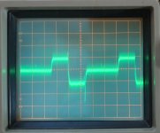
Attenuated or better "slanted edges" steps. Any lowpass filter, even first order will turn each step into this:
Trace A is the non-lowpassed step, Trace B with lowpass. so instead of a nice, crisp sharp edge staircase, you get a "worn stairs" result that looks more like the 1,000 steps up to the Wat on top of the mountain you climb to make merit, cut into the living rock a few 100 Years ago and never refurbished with nice concrete...
Now Wat or is that What (Wat is Temple in Thai) I am trying to achieve with the filter is nothing like AOTA, though being a lowpass it will also have some parallel effects.
Finally, for no reason in particular, a picture of a giant snake coming down from a serious acid trip, it's about 20 min drive from my place.
It illustrates a nice, crip edge staircase in front of it. Not worn at all.
Thor
- Home
- Source & Line
- Digital Line Level
- Building the ultimate NOS DAC using TDA1541A