Not happy with the result, lost high detail. Compare with using 470pf.
I notice the waveform with mine at pin 16 or 17 is different from what your's from the last bottom one. Using your latest dem clock circuit.
Don't know where I have done wrong.
I notice the waveform with mine at pin 16 or 17 is different from what your's from the last bottom one. Using your latest dem clock circuit.
Don't know where I have done wrong.
Attachments

Last edited:
Following EC's other DEM clock thread:
One solution for this problem is preventing the DEM oscillator from oscillating:
pin 16 > 2K2 resistor > -15V
pin 17 > 2K2 resistor > -15V
Then injecting a DEM clock that runs fully synchronous with the bit clock (176.4 KHz, 352.8 KHz, 705.6 KHz, 1.4112 MHz or 2.8224 MHz.).
This is done by creating both a non-inverted and an inverted low jitter clock 352.8 KHz for example). Then injecting these two signals as follows:
non-inverting clock > 10K Ohm > pin 16
inverting clock > 10K Ohm > pin 17
DEM clock frequency also depends on active divider decoupling cap properties and placement. It's best to use smallest possible (SMD) film caps, and use shortest possible connections (every mm counts here). It's also possible to solder the active divider decoupling caps directly to the TDA1541A pins, and route the capacitor GND connections straight to pin 5 (analogue ground).
External DEM clock frequencies of up to 2.8224 MHz are possible when active divider decoupling is done correctly.
Now the DEM oscillator circuit is forced to run in sync with the external DEM clock, this eliminates inter-modulation, greatly reduces DEM clock jitter, and improves time averaging, resulting in lower bit errors.
I changed the latest to this,
Removed D2, R4, R5. U1 pin3 to U3 pin1,2.
Removed R1, D1. U3 power supply pins (7 and 14) to 5V.
TDA1541s
pin 16
pin 17
U3 pin6 non-inverting clock > 10K Ohm > pin 16 > 2K2 resistor > -15V
U3 pin3,4,5,inverting clock > 10K Ohm > pin 17 > 2K2 resistor > -15V
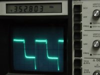
Attached a picture of waveform, freq and voltage at pin16.
I got great sound from this, please tell me if this circuit is ok?
One solution for this problem is preventing the DEM oscillator from oscillating:
pin 16 > 2K2 resistor > -15V
pin 17 > 2K2 resistor > -15V
Then injecting a DEM clock that runs fully synchronous with the bit clock (176.4 KHz, 352.8 KHz, 705.6 KHz, 1.4112 MHz or 2.8224 MHz.).
This is done by creating both a non-inverted and an inverted low jitter clock 352.8 KHz for example). Then injecting these two signals as follows:
non-inverting clock > 10K Ohm > pin 16
inverting clock > 10K Ohm > pin 17
DEM clock frequency also depends on active divider decoupling cap properties and placement. It's best to use smallest possible (SMD) film caps, and use shortest possible connections (every mm counts here). It's also possible to solder the active divider decoupling caps directly to the TDA1541A pins, and route the capacitor GND connections straight to pin 5 (analogue ground).
External DEM clock frequencies of up to 2.8224 MHz are possible when active divider decoupling is done correctly.
Now the DEM oscillator circuit is forced to run in sync with the external DEM clock, this eliminates inter-modulation, greatly reduces DEM clock jitter, and improves time averaging, resulting in lower bit errors.
I changed the latest to this,
Removed D2, R4, R5. U1 pin3 to U3 pin1,2.
Removed R1, D1. U3 power supply pins (7 and 14) to 5V.
TDA1541s
pin 16
pin 17
U3 pin6 non-inverting clock > 10K Ohm > pin 16 > 2K2 resistor > -15V
U3 pin3,4,5,inverting clock > 10K Ohm > pin 17 > 2K2 resistor > -15V
Attached a picture of waveform, freq and voltage at pin16.
I got great sound from this, please tell me if this circuit is ok?
Attachments

Last edited:
Hi fastvideo,
The signals measured on both pin 16 and 17 don't guarantee that the on-chip DEM clock circuits "follow" the external clock signal.
Easiest way to check is disconnecting one of the decoupling caps (100nF) and measure the signal on this now non-decoupled active divider output (set the scope to 10mV AC). You can use pin 12 for example.
The signal should look like a kind of staircase signal with up to 4 different levels. The steps are a result of tolerances in the passive divider that feeds 4 almost equal currents in the DEM averaging logic.
Today I did some more experiments with DEM clock as I plan to build a TDA1541A-based SD-player as well.
In order to minimize interference, DEM clock frequency should preferably be equal to the on-chip clock signals. This basically means either bit clock (2.8224 MHz) or word select (44.1 KHz). The bit clock frequency turned out to be too high to achieve accurate averaging (parasitic capacitances). So I used 44.1 KHz instead, and this worked much better than expected.
My idea was to figure out a way to inject this 44.1 KHz clock into the DEM circuit using only a single signal. I finally succeeded by connecting a resistor in series with a Schottky diode between word select signal and TDA1541A pin 16 (pin 17 is left unconnected). This way no extra logic is required, and the circuit can be used to easily synchronize the DEM clocks of multiple TDA15411A chips (one of these circuits required for each DAC chip).
The value of the resistor is critical and exact values must be used as there is only a narrow "window" of correct operation. Slightly higher or lower resistor values will result in a non-operational DEM clock circuit. This is because I trigger the on-chip DEM clock using varying current.
I performed multiple tests with different TDA1541A chips. Here are the values that provided reliable operation with my prototype setup:
3V3 drive signal (WS): Schottky diode (BAT43) anode connected to this drive signal, cathode (ring) connected to 13 K Ohm resistor, resistor connects to pin 16. Pin 17 not connected.
5V drive signal (WS): Schottky diode (BAT43) anode connected to this drive signal, cathode (ring) connected to 17 K Ohm resistor, resistor connects to pin 16. Pin 17 not connected.
For other drive signal amplitudes, experiment with series resistor value. I used a 10K fixed resistor in series with a 10K potentiometer to determine max. and min value for correct operation. The fixed resistor value should then be between these two limiting values.
Because the DEM logic now runs much more relaxed (much lower oscillator frequency) on-chip ground-bounce is reduced and the DEM clock runs fully synchronous with the word clock (and bit clock).
The existing 100nF decoupling cap value should be increased to approx. 470nF, but the existing 100nF decoupling caps still seem to work fine with 44.1 KHz DEM clock rate (very low ripple voltage).
While at it, I modified I2S attenuators too. Problem was pollution of the 5V DAC power supply because the I2S attenuators were connected to this supply. I inserted some chokes to reduce this effect but this still wasn't optimal. Now I use a series circuit consisting of diodes and a LED to set the voltage levels.
The analogue circuit was next. I wanted to use passive I/V conversion with the highest possible output signal (while keeping distortion low). I ended up using a 140 Ohm I/V resistor (between TDA1541A output and GND). Without further measures this will result in massive distortion as the output signal clips on the lower side. This can be solved by injecting a bias current (on the DAC output pin). I used a 1 K Ohm resistor in series with a hybrid choke connected to +5V. This way one can squeeze around 550mVpp directly out of the TDA1541A while maintaining low distortion. Then it's quite easy to amplify this signal to a suitable level to drive a power amp.
The DC offset voltage across the I/V resistor equals approx 50mV.
The power supplies (+5V, -5V, and -15V) are discrete filtered LED referenced series regulators with integrated filtered precision current source to bias the LED reference.
The TDA1541A was connected to a SD-player PCB (bit clock 1.4112 MHz, word clock 44.1 KHz, and DATA).
I plan to post schematics of this new TDA1541A application soon.
Attached a picture of waveform, freq and voltage at pin16.
I got great sound from this, please tell me if this circuit is ok?
The signals measured on both pin 16 and 17 don't guarantee that the on-chip DEM clock circuits "follow" the external clock signal.
Easiest way to check is disconnecting one of the decoupling caps (100nF) and measure the signal on this now non-decoupled active divider output (set the scope to 10mV AC). You can use pin 12 for example.
The signal should look like a kind of staircase signal with up to 4 different levels. The steps are a result of tolerances in the passive divider that feeds 4 almost equal currents in the DEM averaging logic.
Today I did some more experiments with DEM clock as I plan to build a TDA1541A-based SD-player as well.
In order to minimize interference, DEM clock frequency should preferably be equal to the on-chip clock signals. This basically means either bit clock (2.8224 MHz) or word select (44.1 KHz). The bit clock frequency turned out to be too high to achieve accurate averaging (parasitic capacitances). So I used 44.1 KHz instead, and this worked much better than expected.
My idea was to figure out a way to inject this 44.1 KHz clock into the DEM circuit using only a single signal. I finally succeeded by connecting a resistor in series with a Schottky diode between word select signal and TDA1541A pin 16 (pin 17 is left unconnected). This way no extra logic is required, and the circuit can be used to easily synchronize the DEM clocks of multiple TDA15411A chips (one of these circuits required for each DAC chip).
The value of the resistor is critical and exact values must be used as there is only a narrow "window" of correct operation. Slightly higher or lower resistor values will result in a non-operational DEM clock circuit. This is because I trigger the on-chip DEM clock using varying current.
I performed multiple tests with different TDA1541A chips. Here are the values that provided reliable operation with my prototype setup:
3V3 drive signal (WS): Schottky diode (BAT43) anode connected to this drive signal, cathode (ring) connected to 13 K Ohm resistor, resistor connects to pin 16. Pin 17 not connected.
5V drive signal (WS): Schottky diode (BAT43) anode connected to this drive signal, cathode (ring) connected to 17 K Ohm resistor, resistor connects to pin 16. Pin 17 not connected.
For other drive signal amplitudes, experiment with series resistor value. I used a 10K fixed resistor in series with a 10K potentiometer to determine max. and min value for correct operation. The fixed resistor value should then be between these two limiting values.
Because the DEM logic now runs much more relaxed (much lower oscillator frequency) on-chip ground-bounce is reduced and the DEM clock runs fully synchronous with the word clock (and bit clock).
The existing 100nF decoupling cap value should be increased to approx. 470nF, but the existing 100nF decoupling caps still seem to work fine with 44.1 KHz DEM clock rate (very low ripple voltage).
While at it, I modified I2S attenuators too. Problem was pollution of the 5V DAC power supply because the I2S attenuators were connected to this supply. I inserted some chokes to reduce this effect but this still wasn't optimal. Now I use a series circuit consisting of diodes and a LED to set the voltage levels.
The analogue circuit was next. I wanted to use passive I/V conversion with the highest possible output signal (while keeping distortion low). I ended up using a 140 Ohm I/V resistor (between TDA1541A output and GND). Without further measures this will result in massive distortion as the output signal clips on the lower side. This can be solved by injecting a bias current (on the DAC output pin). I used a 1 K Ohm resistor in series with a hybrid choke connected to +5V. This way one can squeeze around 550mVpp directly out of the TDA1541A while maintaining low distortion. Then it's quite easy to amplify this signal to a suitable level to drive a power amp.
The DC offset voltage across the I/V resistor equals approx 50mV.
The power supplies (+5V, -5V, and -15V) are discrete filtered LED referenced series regulators with integrated filtered precision current source to bias the LED reference.
The TDA1541A was connected to a SD-player PCB (bit clock 1.4112 MHz, word clock 44.1 KHz, and DATA).
I plan to post schematics of this new TDA1541A application soon.
Dear all,
Yesterday I succeeded at building an USB isolator based on ADUM4160 chip that I bought at a very interesting price from circuits@home (Oleg is a great guy). This solution may not be optimal but surely improves the sound!
Cleaner and with better timbre reproduction.
Highly recommended!
USB Isolator. « Circuits@Home
Dear all,
Yesterday I succeeded at building an USB isolator based on ADUM4160 chip that I bought at a very interesting price from circuits@home (Oleg is a great guy). This solution may not be optimal but surely improves the sound!
Cleaner and with better timbre reproduction.
Highly recommended!
USB Isolator. « Circuits@Home
That's great maxlorenz, what speed are you using it at - 16/44, I presume?
I was told it wouldn't work on a high-speed(480Mb/s) device even if the data stream is running at full-speed (12Mb/s). I guess high-speed doesn't negotiate down to full-speed based on the datastream.
That's great maxlorenz, what speed are you using it at - 16/44, I presume?
Thanks, JKeny. I run it through Ubuntu (not RT) at 16bits/44,1KHz, the number of USB packages set to 1, as per Soundcheck's recommendation. I'm afraid that's the farthest my knowledge goes 😀
maxlorenz, are you running it on a laptop? Does it sound the same as running your laptop off batteries? Does adding this to a laptop running on battery improve the sound also?
I got mine in the post yesterday but just the pcb + ADUM chip - need to collect the parts as I'll be running my own external 5V
I got mine in the post yesterday but just the pcb + ADUM chip - need to collect the parts as I'll be running my own external 5V
I have not tried the options you mention yet, but from memory, running the laptop on batteries only improved a HF hiss when listening close to the tweeter...
Is it always good to have a stock of 100nF XR7 SMD and low value SMD resistors. 😎
I used 22R instead of 24R. I hope this is not critical...
Good luck.
M
I got mine in the post yesterday but just the pcb + ADUM chip - need to collect the parts as I'll be running my own external 5V
Is it always good to have a stock of 100nF XR7 SMD and low value SMD resistors. 😎
I used 22R instead of 24R. I hope this is not critical...
Good luck.
M
Is there anywhere that sells a mixed bag of smd caps & smd resistors for a reasonable price?I have not tried the options you mention yet, but from memory, running the laptop on batteries only improved a HF hiss when listening close to the tweeter...
Is it always good to have a stock of 100nF XR7 SMD and low value SMD resistors. 😎
I used 22R instead of 24R. I hope this is not critical...
Good luck.
M
Is there anywhere that sells a mixed bag of smd caps & smd resistors for a reasonable price?
You can find 0.1uf 1206 ceramic caps in almost any piece of old computer equipment; CD-ROM drives from 80s are the best. With luck, low value resistors can be also sourced from therm. 1M resistors are not critical and can be any value; per datasheet, control pins can be even tied to VDDx directly, however, if you want to be able to perform "delayed enumeration" maneuver, make one pulling up PIN pin at least 10K.
Hi CCschua,
Looks like you have the same DAC as I am using as a "test" for some of the things that are being suggested on this Thread by ECDesigns.
depending on your source, you may want to try this sync reclocker for the slim devices squeezebox:
Audio Gestalt
all credit to John Swenson for the above
This totally transformed this DAC, to an even greater degree that any of the other mods I have tried.
Brad
Hi Brad
would you post schematic of your ultimate dac regarding reclocking I2S and DEM
hi Samoloko,
i was really pleased with the reclocker that John Swenson put together in that blog - the link is in the post that you quoted above under "audiogesalt"
it takes a couiple of hours to build and is relatively low cost. I am now using one of Johns/ecdesigns D14 DACs which uses a SPDIF receiver with one of Johns tracker modules, which does a similar job of the reclocker.
Brad
Hi gaetan8888,
For 2x and 4x interpolation only a single CD4517 is required. Not all brands are fast enough @5V power supply, TI works fine.
The propagation delay of the CD4000 series doesn't require to invert BCK when running @ 44.1 KHz.
Bit clock will remain low for 177ns, CD4517 propagation delay (TI) equals approx. 200ns typical, so this is similar to inverting BCK.
This timing is important as it determines the exact moment the DATA or WS signal is stable. The TDA154x latches both WS and DATA on the positive going edge of BCK, the 4517 does the same, and without propagation delay or bit clock inversion, both DATA and WS could change on the exact moment BCK goes high. This would cause data corruption.
But because of the propagation delay, both data and ws signals appear on the shiftregister outputs approx. 200ns later. This means that both DATA and WS from the shift-registers are stable when the bit clock goes high, so the TDA154x chip will clock-in valid data.
The CD4571 has 2 separate 64-bit shift registers with taps on every 16th output (16, 32, 48, and 64).
In order to latch all connected DAC chips on the positive going edge of BCK, a pre-delay of 16 pulses can be used.
2x interpolation (2x TDA1543 / TDA1541A)
Register #1, data input to DATA, DAC chip #1 data input to output16, DAC chip #2 data input to output48
Register #2, data input to WS, DAC chip #1 WS input to output16, DAC chip #2 WS input to output48.
4x interpolation (2x TDA1543 / TDA1541A)
Register #1, data input to DATA, DAC chip #1 data input to output16, DAC chip #2 data input to output48, DAC chip #3 data input to output 32, DAC chip #4 data input to output64.
Register #2, data input to WS, DAC chip #1 WS input to output16, DAC chip #2 WS input to output48, DAC chip #3 WS input to output 32, DAC chip #4 WS input to output64.
Note that the bit clock / WS frequency are limited due to CD4517 specifications. TI specifies minimum 3MHz, and typical 6MHz @5V, so 44.1/16 operation is guaranteed (2.8224 MHz).
Hello John
For the 2x interpolation circuit, how can I check, with an oscilloscope, if the sampling frequency and propagation delay of my circuit are ok, to check if I've made any error and that my circuit work correctly ?
And my oscilloscope seem to have difficulty to pick up the frequency of the output signal of the dac at the IV resistor.
I have a sencore sc61 oscilloscope with an integrated frequency counter.
Thank
Bye
Gaetan
Last edited:
Hi gaetan8888
First you need a suitable 1 KHz 0dB sine wave test signal (test CD).
Next check if step interval matches theoretical frequency, for example with 44.1 KHz source, 2 x interpolation should result in 88.2 KHz (11.338us), and 176.4 KHz (5.669us).
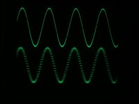
When interpolation functions correctly you should notice an increase in resolution, and a proportional increase in volume level with each added DAC chip. I attached an oscillogram that shows correct operation of the interpolator (upper trace) and 44.1/16 NOS (lower trace).
For the 2x interpolation circuit, how can I check, with an oscilloscope, if the sampling frequency and propagation delay of my circuit are ok, to check if I've made any error and that my circuit work correctly ?
First you need a suitable 1 KHz 0dB sine wave test signal (test CD).
Next check if step interval matches theoretical frequency, for example with 44.1 KHz source, 2 x interpolation should result in 88.2 KHz (11.338us), and 176.4 KHz (5.669us).
When interpolation functions correctly you should notice an increase in resolution, and a proportional increase in volume level with each added DAC chip. I attached an oscillogram that shows correct operation of the interpolator (upper trace) and 44.1/16 NOS (lower trace).
Attachments
Hi gaetan8888
First you need a suitable 1 KHz 0dB sine wave test signal (test CD).
Next check if step interval matches theoretical frequency, for example with 44.1 KHz source, 2 x interpolation should result in 88.2 KHz (11.338us), and 176.4 KHz (5.669us).
When interpolation functions correctly you should notice an increase in resolution, and a proportional increase in volume level with each added DAC chip. I attached an oscillogram that shows correct operation of the interpolator (upper trace) and 44.1/16 NOS (lower trace).
Hello John
Where did you pick-up, in the circuit, the interpolator signal ?
Why the 44.1/16 NOS (lower trace) signal look harsh on your scope image ?
I include an image of the schematic of the circuit that I've used.
Thank you
Bye
Gaetan
Attachments
Last edited:
THD figures trough FFT tests reveals
I have now catched up with my own work and are right at this spot now 🙂
550mVpp is the same as195mV rms. Today I did distortion tests at -0dB with 120 ohm and got 168mV which corresponds to about 474 mVpp. Allready at that lower level the FFT signal had spikes all troughout starting at -50dB.
Not very clean IMO. I tested 100 ohm which is not safe THD wise either. At 66 ohm I was safe with left ch. at -95 worst spike and right ch. no spike at all. -100dB together with other rubbish there. Maybe one could try 82 ohm and look att the FFT but not me. I have gone trough a very exhaustive "program" the last few days
That is way to much. At 0db it is OK but you get distortion at -60dB test signals. Try to measure and you will see. You can also hear it on silent passages in music where there are airgaps sometimes (classic) 😉
Less then 10mV is to shoot for. Thats acceptable i have dicovered. so I adjust my CCS to be withing 1mV.
Also 66 ohm is safe for one TDA1541A. If you paralell TDA's you have to lower that to 33 ohm for two TDA's, 15 ohm for four and so on...
Hi -ecdesign-The analogue circuit was next. I wanted to use passive I/V conversion with the highest possible output signal (while keeping distortion low). I ended up using a 140 Ohm I/V resistor (between TDA1541A output and GND). Without further measures this will result in massive distortion as the output signal clips on the lower side. This can be solved by injecting a bias current (on the DAC output pin). I used a 1 K Ohm resistor in series with a hybrid choke connected to +5V. This way one can squeeze around 550mVpp directly out of the TDA1541A while maintaining low distortion. Then it's quite easy to amplify this signal to a suitable level to drive a power amp.
I have now catched up with my own work and are right at this spot now 🙂
550mVpp is the same as195mV rms. Today I did distortion tests at -0dB with 120 ohm and got 168mV which corresponds to about 474 mVpp. Allready at that lower level the FFT signal had spikes all troughout starting at -50dB.
Not very clean IMO. I tested 100 ohm which is not safe THD wise either. At 66 ohm I was safe with left ch. at -95 worst spike and right ch. no spike at all. -100dB together with other rubbish there. Maybe one could try 82 ohm and look att the FFT but not me. I have gone trough a very exhaustive "program" the last few days
The DC offset voltage across the I/V resistor equals approx 50mV.
That is way to much. At 0db it is OK but you get distortion at -60dB test signals. Try to measure and you will see. You can also hear it on silent passages in music where there are airgaps sometimes (classic) 😉
Less then 10mV is to shoot for. Thats acceptable i have dicovered. so I adjust my CCS to be withing 1mV.
Also 66 ohm is safe for one TDA1541A. If you paralell TDA's you have to lower that to 33 ohm for two TDA's, 15 ohm for four and so on...
Last edited:
If i get this right, this makes every sinewave longer !? Infact this reduce the frequens, and make the sound "false" from the original signal. Of course no existing person in the world can hear this.
It makes the signal transitions smoother, but changes nothing in regards to frequency or shape of the total signal. It only delays the total signal half of the 1/44.1kHz time and smooths out the transitions between each 1/44.1K Hz update.
Reason is the averaging ( integration ) of all the individual DAC signals still accurately recreates the total signal in the time domain. Actual more accurately, because any change in total current output is integrated over the 23 uS period. Current is be add/subtracted every 23uS / (Number Dacs) vs only on the 23uS time slice. It does not add data samples, but smooths the digital step function transitions...
It just smooths things out by filling in the blanks....
jk
Last edited:
It makes the signal transitions smoother, but changes nothing in regards to frequency or shape of the total signal.
It just smooths things out by filling in the blanks....
Sorry, but it adds "wrong" samples. It is linear interpolation. As if you would draw a straight line between two points on a curve. Add a new point in the middle of the line. Where is it ? Not on the curve.
Sorry, but it adds "wrong" samples. It is linear interpolation. As if you would draw a straight line between two points on a curve. Add a new point in the middle of the line. Where is it ? Not on the curve.
My two cents....
I think in terms of total current flow through the I/V resistor....the greater series of approximations due to delaying several DACs more closely matches the real world signal than does the single step function of a single DAC at the 23uSec interval. There are very few step functions in the real world.
Errors? Yes for both a single timed and Linear interpolation DAC. And that can be true for vinyl too. The Linear interpolation is filling in the area under the curve. The single DAC provides a larger single spike of high freq content at the 23uSec interval.
I would also think the signal from a needle in the curve of record can not and does not produce the step functions like single DAC, but it more closely resembles the signal from a linear interpolation DAC , however not exactly.
Even if you put a 44.1k or 15k square wave on vinyl, can a cartridge reproduce it like a singularly timed DAC? What would a Linear interpolation DAC do with 44.1K HZ or 15k square wave? My bet the Linear interpolation DAC behaves and "errors" more like a mechanical system in response to square waves. Not that I listen to square waves...
Just my way of thinking about it.
jk
Last edited:
- Home
- Source & Line
- Digital Line Level
- Building the ultimate NOS DAC using TDA1541A