Hi Zoran
That is the 4 channel version. I use the Vxpocket V2 (= 2ch)
On ebay < usd 100,- !
Onno
Zoran said:You usin something like this?
That is the 4 channel version. I use the Vxpocket V2 (= 2ch)
On ebay < usd 100,- !
Onno
The output stage (push-pull or single-ended) is basically personal taste, and also depends on connected load. I use a single-ended, choke-loaded (10mH / 500R) output with multiple low noise bipolar NPN transistors in parallel for the D1M prototype. The output coupling caps are Vcap TFTF Teflon / Tin caps, these are highly transparent / neutral, but require some burn-in time
Can u show a simple diagram of the choke loaded output ?
I think the VCap TFTF will cost me an arm and a leg. I was considering Mundorf silver/oil but can only afford a 0.22uF.
Hi John,
What sort of value V-CAP TFTF output caps are you using?
is it worth using one higher value Auricap type, by passed with one of those very low value V-CAPS?
Are there any other makes of capacitor that are worth considering that do not hold back the DACs performance?
Brad
What sort of value V-CAP TFTF output caps are you using?
is it worth using one higher value Auricap type, by passed with one of those very low value V-CAPS?
Are there any other makes of capacitor that are worth considering that do not hold back the DACs performance?
Brad
Hi ccschua,
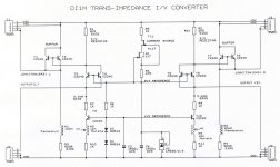
I added the schematics from the converter, used in the D1M.
There are two voltage reference sources that are used for both channels. U2 provides the 2V7 reference voltage, required to get approx. 2.7 - 0.6(Vbe) = 2.1V for the TDA1543 current outputs.
The 2V7 reference voltage also drives a second 1V2 reference source, required for the bias current sources. I am still not sure if sound quality is best, with or without these bias current sources. The voltage references are fed by a cascode current source (T11, T12).
The bias current sources have ferrite beads (from a 10nF Murata filter) in the emitter leads in order to present a relatively high impedance for HF interference signals. This is required to minimize pollution of the DAC output current.
The trans-impedance converter is straight-forward (T3 .. T6). I used transistors in parallel to reduce noise. The I/V resistor quality is VERY important as I/V conversion largely depends on I/V resistor properties. For me personally, only bulk metal film is good enough.
The output buffers are single-ended in order to completely eliminate cross-over distortion and push-pull circuit mismatch. This application also requires current steering (extraction of signal from the I/V resistor), so bipolar transistors had to be used. Again two transistors were placed in parallel to reduce noise. The chokes (N1, and N2) are added to create a high impedance for increasing frequency. This significantly lowers the output power at these frequencies, and will effectively suppress HF interference. The value in the schematic (10mH) can be lowered (depending on connected load).
The required supply voltage is approx. 2V1 plus the max. output signal amplitude (approx. 6Vpp), so minimum supply voltage must be at least 8V1. The output signal amplitude can be increased by increasing both power supply voltage and I/V resistor value.
The TFTF caps are very expensive indeed, and using these only makes sense when your entire audio set is already performing at a very high level. So I suggest to try some cheaper caps first, Intertechnik Audyn plus, or TIN foil are good and affordable, Obligato (dry caps) aren't bad either.
Can u show a simple diagram of the choke loaded output ?
I think the VCap TFTF will cost me an arm and a leg. I was considering Mundorf silver/oil but can only afford a 0.22uF.
I added the schematics from the converter, used in the D1M.
There are two voltage reference sources that are used for both channels. U2 provides the 2V7 reference voltage, required to get approx. 2.7 - 0.6(Vbe) = 2.1V for the TDA1543 current outputs.
The 2V7 reference voltage also drives a second 1V2 reference source, required for the bias current sources. I am still not sure if sound quality is best, with or without these bias current sources. The voltage references are fed by a cascode current source (T11, T12).
The bias current sources have ferrite beads (from a 10nF Murata filter) in the emitter leads in order to present a relatively high impedance for HF interference signals. This is required to minimize pollution of the DAC output current.
The trans-impedance converter is straight-forward (T3 .. T6). I used transistors in parallel to reduce noise. The I/V resistor quality is VERY important as I/V conversion largely depends on I/V resistor properties. For me personally, only bulk metal film is good enough.
The output buffers are single-ended in order to completely eliminate cross-over distortion and push-pull circuit mismatch. This application also requires current steering (extraction of signal from the I/V resistor), so bipolar transistors had to be used. Again two transistors were placed in parallel to reduce noise. The chokes (N1, and N2) are added to create a high impedance for increasing frequency. This significantly lowers the output power at these frequencies, and will effectively suppress HF interference. The value in the schematic (10mH) can be lowered (depending on connected load).
The required supply voltage is approx. 2V1 plus the max. output signal amplitude (approx. 6Vpp), so minimum supply voltage must be at least 8V1. The output signal amplitude can be increased by increasing both power supply voltage and I/V resistor value.
The TFTF caps are very expensive indeed, and using these only makes sense when your entire audio set is already performing at a very high level. So I suggest to try some cheaper caps first, Intertechnik Audyn plus, or TIN foil are good and affordable, Obligato (dry caps) aren't bad either.
Attachments
Hi Builder Brad,
I am using V-Cap TFTF 2uF / 600V DC at the moment. The connected load is approx. 20 K Ohms.
I tried Auricap, and was not impressed, long burn-in didn't help either.
Good (transparent / neutral) capacitors don't require a bypass cap.
If you use a bypass cap, use lowest possible value compared to the main capacitor value, this reduces the risk of resonance between both caps. The bypass cap has to be carefully selected, only specific types / brands will work optimally with a given main cap. I used 1nF Vishay precision polypropylene bypass for 3.3uF Audyn plus. The bypass cap mainly improves transient impulse response, providing slightly better micro-detail, they certainly won't turn an average quality main cap into a stellar performer.
I used Intertechnik plus / Tin foil before testing the Vcaps. Obligato cap's aren't bad either, but they require a lot of space. I look for best transparency / neutrality rather than "spectacular" sounding capacitors that color the sound.
What sort of value V-CAP TFTF output caps are you using?
is it worth using one higher value Auricap type, by passed with one of those very low value V-CAPS?
Are there any other makes of capacitor that are worth considering that do not hold back the DACs performance?
I am using V-Cap TFTF 2uF / 600V DC at the moment. The connected load is approx. 20 K Ohms.
I tried Auricap, and was not impressed, long burn-in didn't help either.
Good (transparent / neutral) capacitors don't require a bypass cap.
If you use a bypass cap, use lowest possible value compared to the main capacitor value, this reduces the risk of resonance between both caps. The bypass cap has to be carefully selected, only specific types / brands will work optimally with a given main cap. I used 1nF Vishay precision polypropylene bypass for 3.3uF Audyn plus. The bypass cap mainly improves transient impulse response, providing slightly better micro-detail, they certainly won't turn an average quality main cap into a stellar performer.
I used Intertechnik plus / Tin foil before testing the Vcaps. Obligato cap's aren't bad either, but they require a lot of space. I look for best transparency / neutrality rather than "spectacular" sounding capacitors that color the sound.
Hi EC,
I think we need to learn how to DIY teflon caps! 😀
About D1M, I am about to try a simpler version trans-impedance (one you posted) DAC on my CD-PRO.
I made a quick measurement on CD PRO's I2S out and found +/-2Vpp for BCK and +/-200mVpp for DATA (I could not retrieve Word select; maybe a bad joint), so I may go without attenuators.
The low DATA signal puzzled me but I had a working TDA1543 dac there years ago...
A question; for your very high gain gyrators, do you make some especial tricks to avoid oscillation?
Cheers,
M
I am using V-Cap TFTF 2uF / 600V DC at the moment. The connected load is approx. 20 K Ohms.
I think we need to learn how to DIY teflon caps! 😀
About D1M, I am about to try a simpler version trans-impedance (one you posted) DAC on my CD-PRO.
I made a quick measurement on CD PRO's I2S out and found +/-2Vpp for BCK and +/-200mVpp for DATA (I could not retrieve Word select; maybe a bad joint), so I may go without attenuators.
The low DATA signal puzzled me but I had a working TDA1543 dac there years ago...
A question; for your very high gain gyrators, do you make some especial tricks to avoid oscillation?
Cheers,
M
Hi ecsdesign
Hallo John
I was nervous when read the end of the DI4T story
I read it fast, maybe something missing too
As i know last time, we plan to get the "battery" PSU
but as i read before, The DI4T not perform well
I just think with another way
- Maybe the PSU not perform well and made crash to DACS
- Cause it was a new invention so we didnt test it enough
- Even had a noise maybe the reg / super reg perform your DACS more
maybe we can try this :
Use the real battery supply to change the battery PSU for a while
http://www.diyaudio.com/forums/showthread.php?s=&postid=1778921#post1778921
Or try some regulator to get the better result
maybe it is ok to get a little noise but have a lot of performance
I got little question, if your DACS got a clock, do we need to
reclocking our CD too ?
Hi maxlorenz,
Don't laugh, but I already constructed some DIY "Teflon" caps last year (only low values like 47pF), using plain Teflon tape (plumbing) and very thin copper foil. They weren't bad at all, but the soft Teflon tape easily causes short-circuit (sharp edges of the copper foil, and the wires soldered to the copper foil).
The DATA signal amplitude varies with the digital audio data content.
No special tricks, just short connections.
I think we need to learn how to DIY teflon caps!
Don't laugh, but I already constructed some DIY "Teflon" caps last year (only low values like 47pF), using plain Teflon tape (plumbing) and very thin copper foil. They weren't bad at all, but the soft Teflon tape easily causes short-circuit (sharp edges of the copper foil, and the wires soldered to the copper foil).
The low DATA signal puzzled me but I had a working TDA1543 dac there years ago...
The DATA signal amplitude varies with the digital audio data content.
A question; for your very high gain gyrators, do you make some especial tricks to avoid oscillation?
No special tricks, just short connections.
I do not laugh! That was my very idea too, after making some DIY cables with *bathroom grade* Teflon tape 😀
BTW, now I have a complete *charge transfered* system, from DAC to amp 😎
as I modded Carlos-s AKA Destroyer X DH RII amps...
http://picasaweb.google.com/lh/photo/if0Yt3ku1R4vGDMHNErStA?feat=directlink
I will tell him 🙁
Cheers,
M
BTW, now I have a complete *charge transfered* system, from DAC to amp 😎
as I modded Carlos-s AKA Destroyer X DH RII amps...
http://picasaweb.google.com/lh/photo/if0Yt3ku1R4vGDMHNErStA?feat=directlink
I will tell him 🙁
Cheers,
M
-ecdesigns- said:Hi maxlorenz,
I wish it was that easy, clock buffers increase master clock jitter, the more cascaded buffers the worse this will get. Similar, connecting too many loads (clock buffers) to the master clock gives problems too. Clock buffers have a certain capacitance between both input and output, and there is always (on-chip) ground bounce, meaning that interference can travel both ways.
I currently use following bit clock distribution scheme:
Master clock > bit clock attenuator (330, 330, 100 Ohm) > TDA1543, shortest possible bit clock path.
Master clock > 390 Ohms > UHS buffer > 1K > load.
I now use 3.3V power supply for the TDA1543, so the 5Vpp bit clock needs to be attenuated. Without attenuation, the bit clock will attempt to "lift" TDA1543 3.3V power supply, resulting in increased interference.
The "dirty" loads are connected to the clock buffer using relatively high 1K series resistors, this reduces the power of the interference signals flowing back to the master clock output. I used 390 Ohm series resistor between master clock and buffer for similar reason.
Talking about master clocks, the new multi-rate tracker / master clock prototype module is ready, worked first time. I attached a photograph.
The green part is a sub-miniature relay that toggles between both crystals (11.2896 and 12.288 MHz), the relay gives best performance, the electronic switches I tried increased jitter. The 100,000uF supercap in the center is required, without it, performance drops significantly. The 18-pin chip on the right is the "brains" of the multirate tracker. The required firmware was written by my brother, to give you an idea of his programming skills, he managed to modify the old tracker program in less than a quarter of an hour. Here he said, when he handed me the programmed micro controller, it should work like this. With some disbelief I put the chip in the test circuit, and guess what, the program worked first time.
This is not a straight-forward program, the micro controller runs on the selected master clock in order to minimize interference / inter-modulation. It has to maintain accurate timing for precise frequency measurement, while changing it's own clock frequency through the 12-bit DAC and VCXO. The program has to take into account that the micro could run on 2.8224, 5.6448 MHz, 3.072 MHz, or 6.144 MHz clock frequency. While doing so it has to determine the source sampling speed, and calculate relative correction factor to maintain real-time tracking. The program has to remain stable while toggling between crystals or changing clock division factor.
The picture on the right shows why the component side had only few parts. The VCXO master clock is built around a WF10192 clock chip, and a dual varactor. The power to the crystal is limited. The oscillator produces a nice low jitter sine wave that's then divided to achieve required bit clock. The WF10192 has an integrated divider that provides :1, :2, :4, and :8. The division factor can be set using 2 pins.
The square 100uH chokes are used for power supply filtering.
The module requires a reference clock (256fs) from the SPDIF receiver that runs in slave-clock mode. The module drives a "locked" LED indicating successful lock to applied sampling rate.
There are 3 sub-power supplies, one for the micro, one for the VCXO master clock, and one for the clock buffer. This way, crosstalk between these power supplies can be minimized. Screening will be added later, in order to reduce sensitivity to EM interference.
As you can see, I managed to put this tracker on the same module size as the single frequency tracker.
Yes, when using a balanced DAC (2 x TDA1543), and dual trans-impedance I/V converter / buffer for each channel. These could drive a bridge unity-gain power buffer. This way the output voltage, required at each trans-impedance converter could be halved.
Hi Ecsdesign
Is this masterclock can use as clock in CD too ? Like Shigaclone ?
If the answer is yes, we fell honour if you let us try in our CDP
Regards, Jeffry
Hi Pocoyo,
The DI4T does perform well indeed, feedback and reviews confirmed this. But using multiple DAC chips introduce problems that need to be solved, this complicates design. The tube amplifiers are problematic too (tube selection, required power supplies, and power consumption).
The D1M doesn't share the DI4T problems, so it's easier to construct a DAC that provides similar performance. I know that most people don't like the TDA1543, based on specs, and designs that weren't optimal, but that are used as "reference". Also consider that speakers produce way more distortion than a DAC chip like this,
It's best to minimize jitter at the source, this can be done by synchronous reclocking of I2S or SPDIF signals. When the jitter at the source is lower, it will usualy result in lower jitter at the connected DAC. This is especially important when using a SPDIF receiver, as it might not function correctly when receiving a signal that contains too high timing jitter amplitude. Apart from that, any signal containing jitter, entering a DAC will cause interference. This is why I have come to the conclusion that the best way to go is to integrate a low jitter digital audio source in the DAC and skip the SPDIF interface.
There is no need for that, the Shigaclone just requires a fixed master clock, the tracker isn't required. However, you will need a very clean power supply to feed the clock, this also depends on surrounding circuits (EM radiation). The servo's required in every CD player produce quite some (EM) interference and pollute connected power supplies. The multiple signals / frequencies present in a servo system make it very difficult to generate and maintain a low-jitter clock.
I was nervous when read the end of the DI4T story
I read it fast, maybe something missing too
As i know last time, we plan to get the "battery" PSU
but as i read before, The DI4T not perform well
The DI4T does perform well indeed, feedback and reviews confirmed this. But using multiple DAC chips introduce problems that need to be solved, this complicates design. The tube amplifiers are problematic too (tube selection, required power supplies, and power consumption).
The D1M doesn't share the DI4T problems, so it's easier to construct a DAC that provides similar performance. I know that most people don't like the TDA1543, based on specs, and designs that weren't optimal, but that are used as "reference". Also consider that speakers produce way more distortion than a DAC chip like this,
I got little question, if your DACS got a clock, do we need to reclocking our CD too ?
It's best to minimize jitter at the source, this can be done by synchronous reclocking of I2S or SPDIF signals. When the jitter at the source is lower, it will usualy result in lower jitter at the connected DAC. This is especially important when using a SPDIF receiver, as it might not function correctly when receiving a signal that contains too high timing jitter amplitude. Apart from that, any signal containing jitter, entering a DAC will cause interference. This is why I have come to the conclusion that the best way to go is to integrate a low jitter digital audio source in the DAC and skip the SPDIF interface.
Is this masterclock can use as clock in CD too ? Like Shigaclone ?
There is no need for that, the Shigaclone just requires a fixed master clock, the tracker isn't required. However, you will need a very clean power supply to feed the clock, this also depends on surrounding circuits (EM radiation). The servo's required in every CD player produce quite some (EM) interference and pollute connected power supplies. The multiple signals / frequencies present in a servo system make it very difficult to generate and maintain a low-jitter clock.
DI2 ecsdesign
Why not make DAC with 2 pcs TDA 1541, not multiple just 2 pcs
Regards, Jeffry
-ecdesigns- said:
The DI4T does perform well indeed, feedback and reviews confirmed this. But using multiple DAC chips introduce problems that need to be solved, this complicates design. The tube amplifiers are problematic too (tube selection, required power supplies, and power consumption).
The D1M doesn't share the DI4T problems, so it's easier to construct a DAC that provides similar performance. I know that most people don't like the TDA1543, based on specs, and designs that weren't optimal, but that are used as "reference". Also consider that speakers produce way more distortion than a DAC chip like this,
Why not make DAC with 2 pcs TDA 1541, not multiple just 2 pcs
Regards, Jeffry
Hello
Yes, DAC with only 2 pcs TDA 1541A
There was a schematic in the thread.
I think, in that schematic, it should be ;
Fsync for the first TDA 1541A and FS32 for the second TDA 1541A
Sdata for the first TDA 1541A and SD32 for the second TDA 1541A
??
I would use CD4517BE
Thank
Bye
Gaetan
http://www.diyaudio.com/forums/attachment.php?postid=964927&stamp=1153319421
Attachments
Hi gaetan8888,
For 2x and 4x interpolation only a single CD4517 is required. Not all brands are fast enough @5V power supply, TI works fine.
The propagation delay of the CD4000 series doesn't require to invert BCK when running @ 44.1 KHz.
Bit clock will remain low for 177ns, CD4517 propagation delay (TI) equals approx. 200ns typical, so this is similar to inverting BCK.
This timing is important as it determines the exact moment the DATA or WS signal is stable. The TDA154x latches both WS and DATA on the positive going edge of BCK, the 4517 does the same, and without propagation delay or bit clock inversion, both DATA and WS could change on the exact moment BCK goes high. This would cause data corruption.
But because of the propagation delay, both data and ws signals appear on the shiftregister outputs approx. 200ns later. This means that both DATA and WS from the shift-registers are stable when the bit clock goes high, so the TDA154x chip will clock-in valid data.
The CD4571 has 2 separate 64-bit shift registers with taps on every 16th output (16, 32, 48, and 64).
In order to latch all connected DAC chips on the positive going edge of BCK, a pre-delay of 16 pulses can be used.
2x interpolation (2x TDA1543 / TDA1541A)
Register #1, data input to DATA, DAC chip #1 data input to output16, DAC chip #2 data input to output48
Register #2, data input to WS, DAC chip #1 WS input to output16, DAC chip #2 WS input to output48.
4x interpolation (2x TDA1543 / TDA1541A)
Register #1, data input to DATA, DAC chip #1 data input to output16, DAC chip #2 data input to output48, DAC chip #3 data input to output 32, DAC chip #4 data input to output64.
Register #2, data input to WS, DAC chip #1 WS input to output16, DAC chip #2 WS input to output48, DAC chip #3 WS input to output 32, DAC chip #4 WS input to output64.
Note that the bit clock / WS frequency are limited due to CD4517 specifications. TI specifies minimum 3MHz, and typical 6MHz @5V, so 44.1/16 operation is guaranteed (2.8224 MHz).
There was a schematic in the thread.
I think, in that schematic, it should be ;
Fsync for the first TDA 1541A and FS32 for the second TDA 1541A
Sdata for the first TDA 1541A and SD32 for the second TDA 1541A
For 2x and 4x interpolation only a single CD4517 is required. Not all brands are fast enough @5V power supply, TI works fine.
The propagation delay of the CD4000 series doesn't require to invert BCK when running @ 44.1 KHz.
Bit clock will remain low for 177ns, CD4517 propagation delay (TI) equals approx. 200ns typical, so this is similar to inverting BCK.
This timing is important as it determines the exact moment the DATA or WS signal is stable. The TDA154x latches both WS and DATA on the positive going edge of BCK, the 4517 does the same, and without propagation delay or bit clock inversion, both DATA and WS could change on the exact moment BCK goes high. This would cause data corruption.
But because of the propagation delay, both data and ws signals appear on the shiftregister outputs approx. 200ns later. This means that both DATA and WS from the shift-registers are stable when the bit clock goes high, so the TDA154x chip will clock-in valid data.
The CD4571 has 2 separate 64-bit shift registers with taps on every 16th output (16, 32, 48, and 64).
In order to latch all connected DAC chips on the positive going edge of BCK, a pre-delay of 16 pulses can be used.
2x interpolation (2x TDA1543 / TDA1541A)
Register #1, data input to DATA, DAC chip #1 data input to output16, DAC chip #2 data input to output48
Register #2, data input to WS, DAC chip #1 WS input to output16, DAC chip #2 WS input to output48.
4x interpolation (2x TDA1543 / TDA1541A)
Register #1, data input to DATA, DAC chip #1 data input to output16, DAC chip #2 data input to output48, DAC chip #3 data input to output 32, DAC chip #4 data input to output64.
Register #2, data input to WS, DAC chip #1 WS input to output16, DAC chip #2 WS input to output48, DAC chip #3 WS input to output 32, DAC chip #4 WS input to output64.
Note that the bit clock / WS frequency are limited due to CD4517 specifications. TI specifies minimum 3MHz, and typical 6MHz @5V, so 44.1/16 operation is guaranteed (2.8224 MHz).
Hi gaetan8888,
Yes that should work, propagation delay for CD4517 (TI) equals 110ns (10V) and 90ns (15V) typical.
Don't forget I2S attenuators and DEM clock synchronization.
Make sure to use a separate clock buffer for driving the CD4517, and use good power supply decoupling (create separate impedance zone). This is required because 128 flip-flops inside this chip will switch simultaneously and produce plenty of interference.
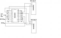
Is it like this ?
I presume that using more than 5 volt supply for the CD4517 would change the the propagation delay.
Yes that should work, propagation delay for CD4517 (TI) equals 110ns (10V) and 90ns (15V) typical.
Don't forget I2S attenuators and DEM clock synchronization.
Make sure to use a separate clock buffer for driving the CD4517, and use good power supply decoupling (create separate impedance zone). This is required because 128 flip-flops inside this chip will switch simultaneously and produce plenty of interference.
Hello John
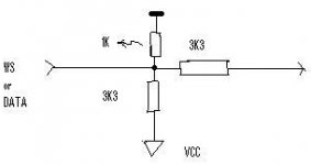
Do I need one I2S attenuators for the WS input and another one for the DATA input of each TDA1541A, and so I would need four I2S attenuators ?
I did found an I2S attenuator done by Max, in the thread, is this one are ok, and I should put 5v on the 3k3 resistor vcc pin ?
I include an image of that I2S attenuator.
And for the clock buffer for driving the CD4517, I could use a 74F00 with the pin 1 for input and the pin 3 for output ?
Thank you
Bye
Gaetan
Attachments
Hi John
Are you continuing with the modular approach for the D1M? If so, might there be an option for a 1541a module to go along with the 1543, or does that become complicated?
Are you continuing with the modular approach for the D1M? If so, might there be an option for a 1541a module to go along with the 1543, or does that become complicated?
Hi gaetan8888,
Yes this attenuator diagram is ok, use one of these for all DATA and WS signals (you will need 4 of these). Then use two more for BCK, but now using lower resistor values. The VCC of these BCK attenuators are connected to 5V using a 10mH choke, and the 330 Ohm resistor Vcc (that's now connected to the 10mH choke), is decoupled to GND using 1500uF/6.3V. This is very important in order to attenuate 5V power supply noise.
74F00 is a NAND gate and it inverts, you need a NON-inverting buffer like the 74F125 for example. These are also available as a single buffer (Fairchild tiny logic series), but these are SMD.
Also use Damping (series) resistors on both buffer input and buffer output. Experiment with 100 Ohm ... 1 K Ohm.
I did found an I2S attenuator done by Max, in the thread, is this one are ok, and I should put 5v on the 3k3 resistor vcc pin ?
Yes this attenuator diagram is ok, use one of these for all DATA and WS signals (you will need 4 of these). Then use two more for BCK, but now using lower resistor values. The VCC of these BCK attenuators are connected to 5V using a 10mH choke, and the 330 Ohm resistor Vcc (that's now connected to the 10mH choke), is decoupled to GND using 1500uF/6.3V. This is very important in order to attenuate 5V power supply noise.
And for the clock buffer for driving the CD4517, I could use a 74F00 with the pin 1 for input and the pin 3 for output ?
74F00 is a NAND gate and it inverts, you need a NON-inverting buffer like the 74F125 for example. These are also available as a single buffer (Fairchild tiny logic series), but these are SMD.
Also use Damping (series) resistors on both buffer input and buffer output. Experiment with 100 Ohm ... 1 K Ohm.
-ecdesigns- said:Hi ccschua,
I added the schematics from the converter, used in the D1M.
There are two voltage reference sources that are used for both channels. U2 provides the 2V7 reference voltage, required to get approx. 2.7 - 0.6(Vbe) = 2.1V for the TDA1543 current outputs.
The required supply voltage is approx. 2V1 plus the max. output signal amplitude (approx. 6Vpp), so minimum supply voltage must be at least 8V1. The output signal amplitude can be increased by increasing both power supply voltage and I/V resistor value.
The TFTF caps are very expensive indeed, and using these only makes sense when your entire audio set is already performing at a very high level. So I suggest to try some cheaper caps first, Intertechnik Audyn plus, or TIN foil are good and affordable, Obligato (dry caps) aren't bad either.
First I notice changing the cap really change the sound a lot. it is very audible. I dispense the Solen and try the Mundorf Elko Glatt and immediately can hear the details more.
Can I know if I use the single ended I/V for the TDA1541A, how to do the CCS since I can only give 0.7V drop across T1. Do u think if I use 2SC2240 (Toshiba) will be better ?
rgds
- Home
- Source & Line
- Digital Line Level
- Building the ultimate NOS DAC using TDA1541A