There is a rectifier bridge (D1 ... D4) using schottky diodes (11DQ10 will be ok too), creating a plus and minus voltage, charging C1 and C2 through D5 ... D8. These diodes are required to create pulsed DC signals for driving both darlingtons, and set the exact switching level. Both R1 and R2 are used to provide a base drive current for the darlington switches. The charge across C1 and C2 is transferred to C3. N1, N2, R3, R4, D9, and D10 are used to attenuate switching noise.
HI ECDesigns,
Can I know what is the wattage for R1=1K and R3= 1R ?
I intend to use SB160 abd BD 680 from Multicomp.
As for the IV transimpedance circuit, I found the push pull design ithe best overall since it gives the most transparent music. I just like the push pull. I also tried a capacitor games. I run it on a project board, I bypass the power supply with 470uF Silmic II and Solen 0.47uF fast cap. found it not bad.
Then I tried 0.47uF alone and found the bass is not so tight anymore.
Hi zoran,
First you must make sure that your specific powerbook G4 supports mini-Toslink (this might be optional, not sure).
Next get a mini Toslink (3.5mm) to Toslink interlink, don't use those adapters as they increase jitter and significantly reduce optical output.
There is a metal (gold-plated) tip on the 3.5mm Toslink "connector". As soon as this Toslink 3.5mm connector is inserted in the earphone socket, it will make contact, and the mac will detect a digital output. Without this plug inserted, it switches to analogue output.
Hope this helps.
I also tryed with a cable one side normal toslink and
another is already for mac hardware, (without adapter)
still nothing changes...
?
this I found for the audio part from poerbook 15in G4 manual
*
Audio System
The 15-inch PowerBook G4 computer supports a audio system with both digital and analog audio. The new optical digital audio input and output capability features Sony/Phillips Digital Interface (S/PDIF) input and output. S/PDIF technology results in a clean audio signal with no added noise to or from an external audio device.
Under the control of the system software, the audio circuitry digitally creates and records sounds. The 15-inch PowerBook G4 computer can receive input only from either the analog input or the digital input. However, it can output simultaneously to digital and analog devices: the internal speaker and combination the headphone out and S/PDIF out port.
By default when components are plugged into the combined optical digital audio output/headphone out port, the audio system mutes the internal speaker.
The headphones and optical digital audio output are only muted when selected in the System Preferences. Muting and audio options are set in System Preferences:Sound:Output.
The analog and digital audio circuitries are not independent. Different audio streams cannot be played to the analog and digital circuitry. The selection of digital or analog output is performed through Sound pane in System Preferences.
The audio circuitry and audio device drivers handle audio data in multiple formats. Both digital and analog audio circuitry handle audio input and output data at sample rates of 32.0 kHz, 44.1 kHz, 48.0 kHz, 64.0 kHz, 88.2 kHz, and 96.0 kHz at sample depths of 16 bits and 24 bits.
If audio data sampled from another computer at a lower rate is played as output on the 15-inch PowerBook G4, the Core Audio (Mac OS X’s OS Level Audio API) transparently up-samples the data to the currently set sampling frequency prior to sending the audio data to the audio circuitry. To maximize audio fidelity, the Core Audio samples are stored as 32-bit floating point. The Sound Manager exists as a Carbon compatibility layer, but developers are encouraged to move their applications to Core Audio for maximum performance and fidelity, because the Sound Manager is capable of representing samples only as 16-bit values.
For more information about audio API’s on Mac OS X, visit the Apple audio technologies developer web page at
http://developer.apple.com/audio/
Optical Digital Audio
The digital I/O circuitry automatically performs input clock recovery on an incoming data stream. This enables bit-accurate copies of the digital data.
Audio signals from the audio input port are converted to digital data internally. All audio is handled digitally inside the computer, including audio data from the CD or DVD drive and from devices connected to the USB and FireWire ports. Audio data is converted to analog form for output to the internal speaker, combination headphones and optical digital audio output, or external speakers.
For details on the optical digital audio input and output electrical specifications, refer to “Audio Line In and Digital Optical Audio Input Specifications” and “Headphone Out and Digital Audio Output Specifications.”
The 15-inch PowerBook G4 computer automatically locks its internal audio hardware to the incoming audio stream to synchronize the audio subsystem to an external device supplying the audio stream. This function allows audio and video to play in sync with the external audio or video device. The data format for signals transmitted over the optical cable is S/PDIF protocol IEC 60958-3.
Since the 15-inch PowerBook G4 does not support a hardware sample rate converter, core audio services provide the sample rate conversion.
External Clocking
When the 15-inch PowerBook G4 computer detects a digital input stream, it is automatically locked to“External” clocking and the computer audio circuitry will track and follow the outgoing digital sampling rate and lock the internal audio hardware to the sampling rate of the external device. The external clock must be stable enough to be locked onto, otherwise the digital circuit will signal an error and the driver will fall back to using the internal clock. The digital input always follows the external clock.
Internal Clocking
When the 15-inch PowerBook G4 computer is set for “Internal” clocking, the computer audio circuitry will run using the computer’s internal clock. Internal clocking is used when there is no digital input.
Audio Inputs
The audio system accepts inputs from the following sources:
?
the built-in microphone
?
the combined optical digital audio input/audio line in port
?
a CD or DVD in the optical drive
?
a digital audio device connected to a USB or FireWire port
The audio line in and optical digital audio input port and the microphone preamp share a dedicated analog input channel in the audio circuitry; the other inputs send digital data. The analog input can be set for play-through or recording. The digital inputs can be selected or mixed by the audio audio circuitry.
The computer also accepts digital audio data from the SuperDrive or from devices connected to the USB or FireWire ports. Audio data from those sources can be sent to the audio system to be converted to analog form for output to the speakers and the combination headphone and optical digital audio output.
Built-in Microphone
The built-in microphone is located on the left speaker grill.
The audio signal from the built-in microphone goes through a dedicated preamplifier that raises its nominal 30 mV level to a nominal 700 mV RMS signal to the audio circuitry. That signal level assures good quality digitizing without driving the analog input into clipping.
Audio Line In and Digital Optical Audio Input Specifications
The combination audio line-in and optical digital audio input is a 3.5 mm mini jack that accepts line-level stereo signals. It also accepts a stereo miniplug-to-RCA cable adapter for connecting stereo equipment to the computer.
The audio line in signal connections are
?
tip: audio left channel
?
ring: audio right channel
?
sleeve: audio ground
Based on playback of a 1 kHz, -1dBFS 24-bit sine wave playback, 24-bit 44.1 kHz output sample rate (unless otherwise specified below) the digital audio input and output have the following electrical characteristics (nominal specifications):
?
Fsi – input sample rates (external clock mode): 32 kHz, 44.1 kHz, 48 kHz, 64 kHz, 88.2 kHz, or 96 kHz
?
Fsi – input sample rate (internal clock mode): 16 kHz – 96 kHz
?
bits per sample: 16-bit or 24-bit
?
SNR (external clock mode): >130 dB
?
SNR: >110 dB
?
THD+N (external clock mode): < -130 dB (0.00003%)
?
THD+N: < -110 dB (0.0003%)
Modem Activity Audio Signals
Modem activity audio signals from the communications slot are sent to the audio circuitry as 8-bit digital data.
Audio Outputs
The audio system sends audio output signals to the built-in speakers and the combination optical digital audio output and headphone out port.
Note: For best results, equipment plugged into the line-out jack should not connect the audio ground to other grounds, such asthe chassis or “green wire” ground.
Headphone Out and Digital Audio Output Specifications
The combination heaphone and optical digital audio output port is located on the left side of the computer. The headphone out provides enough current to drive a pair of low-impedance headphones. It can also be used as a line-level output.
The headphone out has the following electrical characteristics:
?
impedance suitable for driving standard 32-ohm headphones
?
output level 2.0 V peak-to-peak (1.41 V RMS)
?
signal-to-noise (SNR) 90 dB unweighted (typical)
?
total harmonic distortion (THD) 0.01% or less
During playback of a 1KHz, full-scale sine wave (S/PDIF output format, 44.1KHz output sample rate, 24-bit sample depth, unless otherwise specified) the digital audio output has the following nominal specifications:
?
Jack Type: 3.5mm Analog/Optical Combo Jack
?
Output Data Formats: S/PDIF (IEC60958-3), AC3
?
Output Sample Rates: 32KHz, 44.1KHz, 48KHz, 64KHz, 88.2KHz, 96KHz
?
Bits per Sample: 16 or 24 (S/PDIF),16 (AC3)
?
Frequency Response: 20Hz – 20KHz, +/-0dB
?
Signal-to-Noise Ratio (SNR): >130dB
?
Total Harmonic Distortion + Noise (THD+N): <-130dB (0.00003%)
?
Channel Separation: >130dB
Internal Speakers
The computer has two internal speakers, one on either side of the keyboard. The computer turns off the audio signals to the speakers when an external device is actively connected to the optical digital audio /headphone out and during power management.
Digitizing Audio
The audio circuitry digitizes and records audio according to the audio input sample rate and bit depth selected in Audio MIDI setup. If a sound sampled at a higher or lower rate on another computer is played as output, the Sound Manager transparently up-samples or down-samples the sound to the audio output sample rate and bit depth selected in Audio MIDI setup prior to outputting to the audio circuitry.
When recording sound from a microphone, applications that may be affected by feedback should disable sound play-through by calling the Sound Manager functions.

Hi ccschua,
I assume you are referring to the floating charge transfer power supply.
R1 wattage depends on secondary voltage, 0.6 watt metal film should be more than sufficient.
R3 and R4 wattage can be calculated. Suppose the output current equals 0.5A, then the voltage drop would be 0.5V, and the dissipated power 0.5 * 0.5 = 0.25W, so a 0.6W resistor should be sufficient at 500mA output current.
Make sure to remove (bypass) N1 and N2!
The trans-impedance converter requires a very clean power supply (good bypass caps) in order to perform optimally. I use a low noise power supply (around 50nV root Hz), and 22,000uF (supercap) bypass caps. The bypass cap consists of 2 x 47,000uF / 5.5V supercap in series, providing approx. 11 volts.
Use shortest possible connections between DAC chip and trans-impedance converter. Also check your PCB if no other components are still connected to the DAC outputs. GND connection is most important, one slight mistake here, and you can forget about high performance (interference / crosstalk).
Regard the DAC as a RF / HF design (not audio), and apply required design rules. This includes shortest possible connections, un-interrupted ground planes, super-clean power supplies, and correct (local) HF decoupling, using so called impedance zones.
The output stage (push-pull or single-ended) is basically personal taste, and also depends on connected load. I use a single-ended, choke-loaded (10mH / 500R) output with multiple low noise bipolar NPN transistors in parallel for the D1M prototype. The output coupling caps are Vcap TFTF Teflon / Tin caps, these are highly transparent / neutral, but require some burn-in time.
The output coupling capacitor is VERY important, Solen isn't the best choice, and will significantly limit performance.
Can I know what is the wattage for R1=1K and R3= 1R ?
I assume you are referring to the floating charge transfer power supply.
R1 wattage depends on secondary voltage, 0.6 watt metal film should be more than sufficient.
R3 and R4 wattage can be calculated. Suppose the output current equals 0.5A, then the voltage drop would be 0.5V, and the dissipated power 0.5 * 0.5 = 0.25W, so a 0.6W resistor should be sufficient at 500mA output current.
Make sure to remove (bypass) N1 and N2!
As for the IV trans-impedance circuit, I found the push pull design ithe best overall since it gives the most transparent music. I just like the push pull. I also tried a capacitor games. I run it on a project board, I bypass the power supply with 470uF Silmic II and Solen 0.47uF fast cap. found it not bad.
The trans-impedance converter requires a very clean power supply (good bypass caps) in order to perform optimally. I use a low noise power supply (around 50nV root Hz), and 22,000uF (supercap) bypass caps. The bypass cap consists of 2 x 47,000uF / 5.5V supercap in series, providing approx. 11 volts.
Use shortest possible connections between DAC chip and trans-impedance converter. Also check your PCB if no other components are still connected to the DAC outputs. GND connection is most important, one slight mistake here, and you can forget about high performance (interference / crosstalk).
Regard the DAC as a RF / HF design (not audio), and apply required design rules. This includes shortest possible connections, un-interrupted ground planes, super-clean power supplies, and correct (local) HF decoupling, using so called impedance zones.
The output stage (push-pull or single-ended) is basically personal taste, and also depends on connected load. I use a single-ended, choke-loaded (10mH / 500R) output with multiple low noise bipolar NPN transistors in parallel for the D1M prototype. The output coupling caps are Vcap TFTF Teflon / Tin caps, these are highly transparent / neutral, but require some burn-in time.
The output coupling capacitor is VERY important, Solen isn't the best choice, and will significantly limit performance.
Hi zoran,
Have you checked, System preferences > Sound > Output?
This shouldn't be such a problem at all, especially not with a mac.
The user manual refers to the 3.5mm headphone socket for digital output. So this should be the correct socket for mini-Toslink.
If your powerbook G4 version has on-board digital output, it must show up in the system preferences.
Yes EC,
I checked hundered times...
but option bar for digital outout does not apeared..?
*
I have 2 laptop with different OS X
and the same thing about spdif out... nothing at all?
*
I tryed with a adapter
cable without adapter...
and nothing.
*
this should be like this but it is not...
I checked hundered times...
but option bar for digital outout does not apeared..?
*
I have 2 laptop with different OS X
and the same thing about spdif out... nothing at all?
*
I tryed with a adapter
cable without adapter...
and nothing.
*
this should be like this but it is not...
Attachments
BTW
I think that specs for SPDIF on mac
are not bad at all?
*
Fsi – input sample rates (external clock mode): 32 kHz, 44.1 kHz, 48 kHz, 64 kHz, 88.2 kHz, or 96 kHz
Fsi – input sample rate (internal clock mode): 16 kHz – 96 kHz
bits per sample: 16-bit or 24-bit
SNR (external clock mode): >130 dB
SNR: >110 dB
THD+N (external clock mode): < -130 dB (0.00003%)
THD+N: < -110 dB (0.0003%)
*
Zoran said:Yes EC,
I checked hundered times...
but option bar for digital outout does not apeared..?
*
I have 2 laptop with different OS X
and the same thing about spdif out... nothing at all?
*
I tryed with a adapter
cable without adapter...
and nothing.
*
this should be like this but it is not...
Is that screenshot yours?
MacTracker shows that not all PowerBooks G4 have optical out. (www.mactracker.ca )
Jeroen
Hi John,
What a fantastic development with your SD-card player. Even with my
budget Nos-Usb dac and its jittery Burr Brown chip, I'm getting the most enjoyable digital playback I've ever had. I can only imagine how good a rigorously designed Nos DAC with extremely low jitter levels could sound. Never mind all the time and effort saved trying a variety of PC h/w & s/w mods that are really only bandaid solutions.
Back to your DAC. Now that you're stripping away unnecessary modules, will you maintain a modular approach or are you moving towards a single board? I ask because I know you're focussed on designing for the 1543, but having got some 1541a's I was hoping for the option of plugging in your choice of chip.
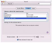
it is not my screen shot...
I have only
first line option.
authomatic recognition of headphones/line out when jack apllyed, and internal speakers when pull-out...
*
without second line digital out
*
third line is from other sofrware option not from mac os x...
I have only
first line option.
authomatic recognition of headphones/line out when jack apllyed, and internal speakers when pull-out...
*
without second line digital out
*
third line is from other sofrware option not from mac os x...
failed...
I have little bit older OS X 10.3.4
and they do not have the version for that just earlyer and later...
tryed at 100 places...
*

I have little bit older OS X 10.3.4
and they do not have the version for that just earlyer and later...
tryed at 100 places...
*
Use shortest possible connections between DAC chip and trans-impedance converter. Also check your PCB if no other components are still connected to the DAC outputs. GND connection is most important, one slight mistake here, and you can forget about high performance (interference / crosstalk).
Hi ECDesigns, your statement really hit the nail right at the spots. I have remove the connecting capacitor and resistor path and a veil is removed. Further, the ground if not properly done up, the crosstalk and hissing noise wil haunt.
After I got those right, yes, it is music in the air. Now I am waiting for Darlington and the schotky to come.
Zoran said:failed...
I have little bit older OS X 10.3.4
and they do not have the version for that just earlyer and later...
tryed at 100 places...
*
According to my version of macTracker :
Only the PowerBook G4 (1.67GHz) introduced in Oct 2005 has dig out.
Mac spdif out
Hi Zoran
I suggest you not to try firewire or usb !!
Your mac powerbook has a pcmcia slot (I think and hope).
I use a pcmcia VXxpoxket V2 soundcard. (Digigram)
It has coax spdif in and out.
On the input I feed it with an external battery powered clock.
(this clock sits in my diy ad converter)
(btw there is no difference between the V2 and the first version only de connection cable differs, the V2 has an extra headphone out in the cable connected to pin 2 from the line xlr outputs !!)
The spdif in and outputs are unbalanced. I balanced it (110 ohm) with a pulse trafo.
I tried all kinds of firewire stuf even the RME Fireface 800 that I happely sold to a rockgroup in Berlin !!. The vxpocket with external clock outperformed them all.
Onno
Hi Zoran
Zoran said:I will try to obtain digital out from the firewire [/B]
I suggest you not to try firewire or usb !!
Your mac powerbook has a pcmcia slot (I think and hope).
I use a pcmcia VXxpoxket V2 soundcard. (Digigram)
It has coax spdif in and out.
On the input I feed it with an external battery powered clock.
(this clock sits in my diy ad converter)
(btw there is no difference between the V2 and the first version only de connection cable differs, the V2 has an extra headphone out in the cable connected to pin 2 from the line xlr outputs !!)
The spdif in and outputs are unbalanced. I balanced it (110 ohm) with a pulse trafo.
I tried all kinds of firewire stuf even the RME Fireface 800 that I happely sold to a rockgroup in Berlin !!. The vxpocket with external clock outperformed them all.
Onno
I am using now Grifin FireWhave...
You could not believe what they put inside...
ohford-s FW970 like interfacing audio from the FW,
and at the end wolfson DA conn.
*
I2S is communication stream...😉
that is what I can extract and feed the DA converter directly...
*
But they are glued the plastic package, so opening is not reversibile process...
*
Digigram VXpocket is look like a great piece...
I am not an expert but it could be said,
and the price folowing this🙄
I am not an expert but it could be said,
and the price folowing this🙄

- Home
- Source & Line
- Digital Line Level
- Building the ultimate NOS DAC using TDA1541A