Guys from ML (Madrigal) or Mark Levinson the man?
I don't know the pre(s) in question (38 / 380).
What I can say is... the best pre I've heard to date was the Jeff Rowland Coherence.
This pre has two boxes: pre and PSU.
The PSU is mains and batteries.😎
My ears liked it, we tested other pres, on the same system, but nothing plays like this one, it's really special.
Anyone with the schematic of this?😀
😎
Jeff Rowland Coherence
Is this one also using the 3310 for volume?
All the Levinson amps i've heard are remarkably sleep inducing. Is this what they call neutral?
analog_sa said:
Is this one also using the 3310 for volume?
All the Levinson amps i've heard are remarkably sleep inducing. Is this what they call neutral?
That's a very good description. A friend of mine who listened to unmodified version said that the sound was "very hypnotizing" 😉
analog_sa said:Is this one also using the 3310 for volume?
Dunno.
Do you have the schematic?😀
What I can tell you is that I've never heard a treble like that.

We tested other pres and the treble seamed splashy compared to this one.
Such a breathtaking definition gives you years of life!😎
Hi Carlos,
After examining the PCB of the ML38S, I found that there are already caps ranging 0.01uF to 0.047uF connecting from the +ve and -ve of the opamps to the ground already. If you look at the photo of the PCB, those Wima green caps surrounding the opamps are the ones that I am talking about. In this respect, only those 0.1 uF connecting between +ve and -ve are missing.
1. Do I still need to add electrolytic caps parallel the 0.01uF between +ve and ground as well as -ve to ground?
2. Or I should pull out those 0.01uF caps and replace them with electrolytic caps?
Sunny
Use the electrolythics from the op-amp's pins to ground.
And the poly between + and -.
I saw very badly bypassed op-amps there, on the pic, but as i don't have the PCB here with me, I can't help much more...
Do your best to put the caps as close as possible to the op-amp's psu pins, on every op-amp.
And the poly between + and -.
I saw very badly bypassed op-amps there, on the pic, but as i don't have the PCB here with me, I can't help much more...
Do your best to put the caps as close as possible to the op-amp's psu pins, on every op-amp.
Dear Carlos,
I'll try to solder ecaps in parallel with the existing 0.01uF on the opamp accordingly.
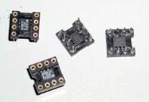
BTW, if I wish to use two single opamps using an adaptor that is being shown in one of my pics
do I need to solder ecap and bypass cap on each single opamp or just solder one ecap and one bypass cap at the adaptor pins?
Sunny
I'll try to solder ecaps in parallel with the existing 0.01uF on the opamp accordingly.
BTW, if I wish to use two single opamps using an adaptor that is being shown in one of my pics
An externally hosted image should be here but it was not working when we last tested it.
do I need to solder ecap and bypass cap on each single opamp or just solder one ecap and one bypass cap at the adaptor pins?
Sunny
Sunsun22 said:do I need to solder ecap and bypass cap on each single opamp...Sunny
Ideally yes...😉
this one does use the CS3310 - previous models used relays and discrete resistors.
sorry, i have no schematics :-(
maybe jam does 🙂
sorry, i have no schematics :-(
maybe jam does 🙂
analog_sa said:Is this one also using the 3310 for volume?
I wish to change the SSM2220 and SSM2210 into MAT02 and MAT03 but I need the TO78 to DIP8 adaptor. Can anyone give me the source for this?
An externally hosted image should be here but it was not working when we last tested it.
Hi All,
I am new in this forum.
I would like to ask you if someone have tried to use Walt Jung super regulator for substitute 7815 and 7915.
is it possible use this regulator? is current enough?
By Miglio
I am new in this forum.
I would like to ask you if someone have tried to use Walt Jung super regulator for substitute 7815 and 7915.
is it possible use this regulator? is current enough?
By Miglio
Very interesting thread, given the old battle of ICs vs. discrete, but since I don't know the ML38 and can find no manual or description, it would be nice if someone could give a short description of the signal chain, in terms of op-amps used etc. from input to output. Volume control in the later versions seems to be CS3310, but isn't there two versions of this chip ???
I also noticed someone suggsting changing some SSMs to MAT 02/03..
Any discrete opamps in there, or MC input ???
I also noticed someone suggsting changing some SSMs to MAT 02/03..
Any discrete opamps in there, or MC input ???
I have taken some time on the original 38 PCB and replaced the eCaps on left channel with all BG caps.
Due to reasons, some values have been changed as follows: -
At the bridge - the original caps were unchanged.
At the regulator - original 2 x 6800uF 35V to BG N 1000uF 35V
After regular - 2 x 68uF 63V to BG std 100uF 50V
Near EL2020 - 2 x 68uF 63V to BG std 47uF 50V (380S changed to 100uF but cannot match 380S value due to size of BG)
Near EL2020 - 8 x 10uF 50V to BG std 33uF 16V (380S changed to 100uF 16V) but cannot match 380S value due to size of BG)
Near LT1217 - 2 x 330uF 25V to BG N 100uF 16V (380S changed to 100uF)
After burning in for 24 hours, I have an impression that the left channel (BG changed) is having more details in the high, more clear in the mid but lack of punch in the low when compared to the untouched right channel. I intended to do either one of the followings: -
1. Increase the value of the caps near EL2020 to BG N 100uF 16V but would need to put hot melts to glue the eCap's bottom to the PCB.
2. Increase the value of the eCap at the regulator to BG N 2 x 1000 uF 35V parallel.
3. Putting extra eCaps (10uF 16V Panasonic FC) on each opamp's +ve and -ve to the ground decouple with 0.1uF 17V BG std.
4. Do nothing, wait longer for the caps to burn in.
Can anyone give me some suggestions that if I am only to choose ONE option. Which option will give the most significant improvement to the low? I am also open for any other suggestions.
Second question is about the polar arrangment of BG N caps. I am just following the orientation of polar caps with the longer lead as +ve.
Is this correct? Or should I choose to have the inner foils connect to the ground?
Thanks
Sunny
Hong Kong
An externally hosted image should be here but it was not working when we last tested it.
Due to reasons, some values have been changed as follows: -
At the bridge - the original caps were unchanged.
At the regulator - original 2 x 6800uF 35V to BG N 1000uF 35V
After regular - 2 x 68uF 63V to BG std 100uF 50V
Near EL2020 - 2 x 68uF 63V to BG std 47uF 50V (380S changed to 100uF but cannot match 380S value due to size of BG)
Near EL2020 - 8 x 10uF 50V to BG std 33uF 16V (380S changed to 100uF 16V) but cannot match 380S value due to size of BG)
Near LT1217 - 2 x 330uF 25V to BG N 100uF 16V (380S changed to 100uF)
An externally hosted image should be here but it was not working when we last tested it.
After burning in for 24 hours, I have an impression that the left channel (BG changed) is having more details in the high, more clear in the mid but lack of punch in the low when compared to the untouched right channel. I intended to do either one of the followings: -
1. Increase the value of the caps near EL2020 to BG N 100uF 16V but would need to put hot melts to glue the eCap's bottom to the PCB.
2. Increase the value of the eCap at the regulator to BG N 2 x 1000 uF 35V parallel.
3. Putting extra eCaps (10uF 16V Panasonic FC) on each opamp's +ve and -ve to the ground decouple with 0.1uF 17V BG std.
4. Do nothing, wait longer for the caps to burn in.
Can anyone give me some suggestions that if I am only to choose ONE option. Which option will give the most significant improvement to the low? I am also open for any other suggestions.
Second question is about the polar arrangment of BG N caps. I am just following the orientation of polar caps with the longer lead as +ve.
An externally hosted image should be here but it was not working when we last tested it.
Is this correct? Or should I choose to have the inner foils connect to the ground?
Thanks
Sunny
Hong Kong
Sorry, mixed up with some values of the 380S. Correct version as follows: -
At the bridge - the original caps were unchanged.
At the regulator - original 2 x 6800uF 35V to BG N 1000uF 35V
After regular - 2 x 68uF 63V to BG std 100uF 50V
Near EL2020 - 2 x 68uF 63V to BG std 47uF 50V (380S changed to 68uF but cannot match 380S value due to size of BG)
Near EL2020 - 8 x 10uF 50V to BG std 33uF 16V (380S changed to 100uF but cannot match 380S value due to size of BG)
Near LT1217 - 2 x 330uF 25V to BG N 100uF 16V (380S changed to 68uF)
For a brief time I tried AD8610 int the main gain stage (insted of OPA627). First impression was that AD chips sounded more musical (OPA seem a bit too mechanical sounding lacking resolution in highs), but after longer listening AD8610 seems too bright. So bright that it's almost annoying. Also, the bass is less than with OPA627. I put OPA chips back and the sound is much more balanced, although less involving, it seems. I might try those LT chips back again.
I also ordered some THS4061/81 as they were reported to sound better than both 8610 and 627.
I also ordered some THS4061/81 as they were reported to sound better than both 8610 and 627.
Attachments
Peter Daniel said:...but after longer listening AD8610 seems too bright.
Yes.😀
Peter Daniel said:So bright that it's almost annoying.
Yeeeeessss.🙂
Peter Daniel said:Also, the bass is less than with OPA627.
Oh yes...😀
Peter Daniel said:I put OPA chips back and the sound is much more balanced...B]
Ah, yes...

Peter Daniel said:...although less involving, it seems. I might try those LT chips back again.
There's a trick to put the OPA627 singing properly.
With standard implementation it sounds a little shut in on the treble.
When (if?) they re-open my thread (the amp one) I will tell ya all how to put this beauty singing like there's no tomorrow.😀
It's just a little detail that makes all the difference.😉
OPA627 trick
OK Carlosfm, so what is the "trick" to get the 627 to sing, cause so far I definately prefer the THS4061-more spacious, better highs. Mids are not as projected, i.e. soundstage is not as deep and bass resolution is slightly poorer than 627, but the THS4061 is still burning in...
Is the trick the JFET bias or the 200pF cap or something else, which I hope you reveal here. No need to wait for the other thread...
The reason I was asking for difference between those two versions is because I tried today BP version (AP was used previously) and it seems like the sound is less mechanical and the highs are more open. I didn't really expect it.
- Home
- Amplifiers
- Solid State
- Building Mark Levinson 38 preamp chassis from scratch