The B version has: lower noise, lower offset voltage, higher open loop gain, better common mode rejection, lower input bias current, higher price 😉
Check out the 2nd page of the datasheet: http://focus.ti.com/lit/ds/symlink/opa627.pdf
Check out the 2nd page of the datasheet: http://focus.ti.com/lit/ds/symlink/opa627.pdf
OPA627BP
I just noticed that Digikey is selling OPA627 at $18.38 and 26.63 for AP and BP respectively. Yet, I brought 4 OPA627BP in HK at only US$15 each. Now, I wonder if I am buying a real OPA627BP considering re-marking WAS very popular in the past for CPU.
Any opamp works in the same circuit except the quality of sound reproduction. Is there any way to find out if I am really buying a real OPA627? Not to say to find out the difference between AP and OP.
Sunny
Re: OPA627 trick
Ok, I'll open a thread for this, on the chipamp forum.
Peter, I also prefer the BP version.
Dr.H said:OK Carlosfm, so what is the "trick" to get the 627 to sing, cause so far I definately prefer the THS4061-more spacious, better highs. Mids are not as projected, i.e. soundstage is not as deep and bass resolution is slightly poorer than 627, but the THS4061 is still burning in...
Is the trick the JFET bias or the 200pF cap or something else, which I hope you reveal here. No need to wait for the other thread...
Ok, I'll open a thread for this, on the chipamp forum.
Peter, I also prefer the BP version.
Re: OPA627BP
If you have any concerns that you are getting original chips, the best bet is probably ordering samples from TI😉
Also, when playing with input gain stage on ML preamp, check the offset after changing chips. It seems that in some cases the offset becomes hard to control.
For instance, after inserting THS4061 chips, I was getting 14mv offset on one of them and 200mv on the other (they work in pairs per channel, 4 pcs total). The situation was the same after I switched the placing of the chips, so the offset was not produced by a chip, but the circuit. This was creating the offset in excess of 2V at the preamp output, depending on volume setting. Both channels were showing the same problem.
Sunsun22 said:Is there any way to find out if I am really buying a real OPA627? Not to say to find out the difference between AP and OP.
If you have any concerns that you are getting original chips, the best bet is probably ordering samples from TI😉
Also, when playing with input gain stage on ML preamp, check the offset after changing chips. It seems that in some cases the offset becomes hard to control.
For instance, after inserting THS4061 chips, I was getting 14mv offset on one of them and 200mv on the other (they work in pairs per channel, 4 pcs total). The situation was the same after I switched the placing of the chips, so the offset was not produced by a chip, but the circuit. This was creating the offset in excess of 2V at the preamp output, depending on volume setting. Both channels were showing the same problem.
I tried resistor biasing OPA627 BP chips. The initial impression was that it brings improvement: better defind midrange, much more open sound and good presence.
But I also noticed some sort of tension in the performance, sort of nervousness, like forced equalisation that wasn't completely natural, maybe some grain as well.
I decided to disconnect resistors, but I cut them off under power on conditions and effectively destroyed all the OPA chips😉. This made me really upset, as I only had AP grade left and BP produced better sonics. I didn't even want to go back to APs, as they were too mechanical sounding.
So I inserted AD8610 chips. Again, it confirmed my previous impression that the sound was just too bright and sort of screatchy. But a thought came up: why not try OPA2604 again for I/V conversion? I previously exchanged it for AD823, because with OPA627 it was much better match (it brought up highs in dull sounding OPA627 chips).
So I placed OPA2604 in I/V stage and finally I started to get AD8610 properly balanced tonally. Both those chips seemed to be more musical (than the other ones) and together, I think they actually perform better than AD823/OPA627 combo.
I ordered new OPA chips in a meantime, so I will have a chance to go back to the previous setup, but I'm not sure if resistor biasing is the best option here. There was something in the presentation that indicated over eqalisation, to the point that I was not completely 'one' with the music😉
I'm getting much better feel of pace and rhythm with the new setup (8610/2604). OPA2604 seems a bit 'blurry' but I believe that could be improved with better bypassing structure, something I didn't address yet.
I am at the final stage of modifying my 38S. Recently, I soldered 0.1uF 50V multilayer ceramic cap from AVX (Farnell parts number 108933) as PSU bypass on each opamp but after listening for a week, the sound remains very tight and mechanical.
The 38S was once quiry airy and vocal is sweet but now, they're gone. Is there any recommendation (that can be available from Farnell) to "soften" the sound? Actually, is it a must to have PSU by pass because I also desoldered all of them and the sound gets better with no denoted noise?
Thanks
Sunny
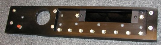
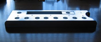
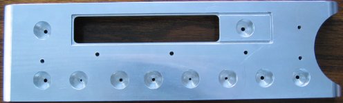
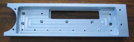
The close up of the hole. Panel thickness is about 1" here, but I did not have any troble using 1 3/4 hole saw for that purpose. My advise is to use one size smaller first (in my case 1 5/8), but not completely through, and then finish with final size. As you see the edge came out very good: clean without any burrs.
Attachments
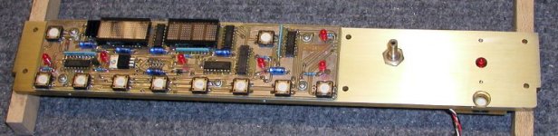
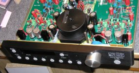
And finally, the knob. This time I went for a different look. This arrangement is similar to ML32 preamp (with an exception that my knob is 1.75, ML32 has 1.5 knob). I was already getting a bit bored by the big 2" knob in center, and this seems to be more refreshing. Took me about 3 hours to fabricate the knob, having aluminum mounted in a drill gun and using belt sander for shaping. I'm pretty much satisfied with a result. Later I etched it and lightly anodised. It will not discolor or stain.
I have more than 50 BG caps in this preamp, mostly N type😉
I have more than 50 BG caps in this preamp, mostly N type😉
Attachments


If you can get white colour as push buttons, " wash " this knob in strong warm solution of NaOH, following by washing in cca 3 - 5 % HNO3 .
Peter I am astonished by your work. 😱 😱 You live in country where everything is possible to find or buy. I will probably spend a six months here in Europe , only to find and buy all premium electronic components and other material for such design. Wonderfull yob. Next your project must be some DIY Sonic Frontiers L1 , Krell or Classe preamp or power amp 
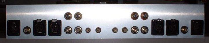
I'm putting together a small group purchase for the ML38 back aluminium identification plate. It will be exactly like the original ML38 plate 😎. A perfect copy, great quality scratch resistant, anodized aluminium with serigraph lettering and holes already drilled with CNC machine. The real thing. I did a high quality (700dpi) image for the lettering using Photoshop and use AutoCAD to provide a dxf file for the drilling. Using Photoshop I reproduced perfectly exactly the same font and font pitch used on the real plate.
On the real ML38, the rear panel is part of the case, 1/8" black anodized aluminium. Then an nice brush aluminium alu plate is installed to identifiy the in/out.
The plate has all the I/O connectors already drilled including the rec/out 4 rca connectors. The holes will accept Cardas GRFA RCA connector. The remote control RJ connectors are identify but not drilled, since most user won't install them anyway.
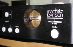
The rear panel will then be identical to this image, See: http://www.marklevinson.com/image_library/380RP_lo.jpg
The nice thing also is that this plate can be use as a drill guide for the structural rear plate.
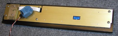
I received today the prototype drill plate without marking. It fits perfectly, see image.
Contact me rapidly if you are interested. I'll place the order by next week.
On the real ML38, the rear panel is part of the case, 1/8" black anodized aluminium. Then an nice brush aluminium alu plate is installed to identifiy the in/out.
The plate has all the I/O connectors already drilled including the rec/out 4 rca connectors. The holes will accept Cardas GRFA RCA connector. The remote control RJ connectors are identify but not drilled, since most user won't install them anyway.
The rear panel will then be identical to this image, See: http://www.marklevinson.com/image_library/380RP_lo.jpg
The nice thing also is that this plate can be use as a drill guide for the structural rear plate.
I received today the prototype drill plate without marking. It fits perfectly, see image.
Contact me rapidly if you are interested. I'll place the order by next week.
Attachments
- Home
- Amplifiers
- Solid State
- Building Mark Levinson 38 preamp chassis from scratch