I choose MOSFETs in this instance for a couple of reasons - first they are fast (the DAC chips themselves are MOS) and second when in common-gate mode the input current is equal to the output current (at least at low enough frequencies). A BJT 'loses' some of the current (comes out of the base) so its less 'accurate'.
MOSFETs don't do the I/V conversion rather they just enhance the DAC chip's voltage handling capability. The HPs themselves do the I/V conversion. In your case with 32R headphones you probably can drive the HPs directly without the MOSFETs as the required voltage swing into 32R is low enough - the DAC can handle 3V swing. I was driving 300R HPs for this project. You still do need to worry about DC, even without MOSFETs though.
MOSFETs don't do the I/V conversion rather they just enhance the DAC chip's voltage handling capability. The HPs themselves do the I/V conversion. In your case with 32R headphones you probably can drive the HPs directly without the MOSFETs as the required voltage swing into 32R is low enough - the DAC can handle 3V swing. I was driving 300R HPs for this project. You still do need to worry about DC, even without MOSFETs though.
My case is with 68R headphones. Still possible without MOSFET's? Are 3V swing still enough then? How many DACs do you think are necessary?
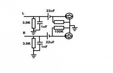
I'm stacking more chips today and see how it goes. My past experience with the Teradak TD1387 8x DAC directly on headphones is that it still needed around +12dB extra, so maybe at least 10x will be necessary. DC decoupling requires an extra resistor to ground between cap (-) and HPs? I see you suggested a 100k to someone with a similar question (see attachment). Is the 22u value of capacitor still correct in my case?
I'm stacking more chips today and see how it goes. My past experience with the Teradak TD1387 8x DAC directly on headphones is that it still needed around +12dB extra, so maybe at least 10x will be necessary. DC decoupling requires an extra resistor to ground between cap (-) and HPs? I see you suggested a 100k to someone with a similar question (see attachment). Is the 22u value of capacitor still correct in my case?
Attachments
You mentioned your HPs were 106dB/mW so I think if you aim for a maximum 116dB SPL that means 10mW and so the current necessary to achieve that is 12mA (peak) hence your total volt swing is only 1.5V. No FETs needed. You'll need 24 DAC chips.
The schematic you're showing is for voltage output so isn't suitable for Iout into HPs.
The schematic you're showing is for voltage output so isn't suitable for Iout into HPs.
For Iout you need a way to make the output current of the DAC chips bipolar. Meaning you need to have both positive and negative currents though the HPs when only positive currents come out of the DAC chips.
How I'd do that is arrange for a sinking current source from DAC output to GND and I'd sit the HP's GND terminal at about half the possible output swing, so ~1.6V in this case. To create a 1.6V reference is a little bit tricky - perhaps you could do it with a TLV431 though I worry about how noisy that'll be. Guess it has to be tried and listened to.
How I'd do that is arrange for a sinking current source from DAC output to GND and I'd sit the HP's GND terminal at about half the possible output swing, so ~1.6V in this case. To create a 1.6V reference is a little bit tricky - perhaps you could do it with a TLV431 though I worry about how noisy that'll be. Guess it has to be tried and listened to.

Wow, we are talking. I'll GLADLY try this out. I can get a TL431 reference at the corner and give it a try. Have to draw a diagram before though...
Just for the sake of clarity (). Why is the total max. output voltage considered as 3V? If 10mW require 12mA, then the voltage at stake in the calculation before is 0.83V (midpoint 0.415V) :s This is also the voltage output of the DAC's vRef. What does the 3V stand for?
Just for the sake of clarity (). Why is the total max. output voltage considered as 3V? If 10mW require 12mA, then the voltage at stake in the calculation before is 0.83V (midpoint 0.415V) :s This is also the voltage output of the DAC's vRef. What does the 3V stand for?
Note that a TL431 isn't the same animal as TLV431. TL431 can't be used to generate below 2.5V, whereas TLV431 can go down to 1.25V.
The total max swing is determined by the DAC chips as 3.5V (assuming 5V supply). 10mW is the peak power, it needs 12mA in either direction so the swing into the HPs is 2*0.012*63 = 1.5V. The mid-point of the DAC swing is 1.75V (3.5/2V) so perhaps that's the ideal voltage setting for the TLV431. The swing at the DAC output pins with the HPs connected will be from +1V to +2.5V.
The total max swing is determined by the DAC chips as 3.5V (assuming 5V supply). 10mW is the peak power, it needs 12mA in either direction so the swing into the HPs is 2*0.012*63 = 1.5V. The mid-point of the DAC swing is 1.75V (3.5/2V) so perhaps that's the ideal voltage setting for the TLV431. The swing at the DAC output pins with the HPs connected will be from +1V to +2.5V.
Uh, a TLV431 I would have to order. Could it be replaced eventually by a resistor voltage divider and an opamp as buffer? I'm thinking on the usual configuration of op-amp based linear voltage regulators, but driven by a resistor divider (over the 5v regulated VDD of the DAC) instead of a zener, to have it more quiet.
So voltage is calculated this way (I deduce): 10mW are needed to reach the desired SPL. Given that the DAC's working vRef is 0.83v, 0.012mA peak are needed to reach that power (V*I=P). Since this headphones are 63ohm, their working peak voltage will be 0.756v (R*I=V). Twice that gives Vpp. 🙂 Right? So the DAC's vref is in any case the base of the calculation, I suppose.
The total max swing is determined by the DAC chips as 3.5V (assuming 5V supply). 10mW is the peak power, it needs 12mA in either direction so the swing into the HPs is 2*0.012*63 = 1.5V. The mid-point of the DAC swing is 1.75V (3.5/2V) so perhaps that's the ideal voltage setting for the TLV431. The swing at the DAC output pins with the HPs connected will be from +1V to +2.5V.
So voltage is calculated this way (I deduce): 10mW are needed to reach the desired SPL. Given that the DAC's working vRef is 0.83v, 0.012mA peak are needed to reach that power (V*I=P). Since this headphones are 63ohm, their working peak voltage will be 0.756v (R*I=V). Twice that gives Vpp. 🙂 Right? So the DAC's vref is in any case the base of the calculation, I suppose.
Yes, that would be an alternative solution.Uh, a TLV431 I would have to order. Could it be replaced eventually by a resistor voltage divider and an opamp as buffer? I'm thinking on the usual configuration of op-amp based linear voltage regulators, but driven by a resistor divider (over the 5v regulated VDD of the DAC) instead of a zener, to have it more quiet.
So voltage is calculated this way (I deduce): 10mW are needed to reach the desired SPL. Given that the DAC's working vRef is 0.83v, 0.012mA peak are needed to reach that power (V*I=P). Since this headphones are 63ohm, their working peak voltage will be 0.756v (R*I=V). Twice that gives Vpp. 🙂 Right? So the DAC's vref is in any case the base of the calculation, I suppose.
The DAC's Vref doesn't play any part in the calculation, only the output current. The peak current is 0.012A (not mA) from P=I*I*R.
Wow, that formula was not in my books yet. Thanks, I get the maths now.
I'm working on the diagram and I have a problem with the current sink. Since it uses NPN transistor(s), voltage will go down 0.6v regarding the 1.5vpp of the DAC output. Therefore headphones will only be able to draw 0.9vpp 😕 Also, I interpret that a current sink with 2 NPNs makes current constant, whereas a single NPN only sinks current but makes it variable to load. I don't know which topology is needed.
Also, I suppose the current sink (in case constant) should let pass 24mA, right? The total consumption of the headphones.
The current sink could be either a single NPN or two NPN transistors. It needs to be 12mA to GND to offset the unipolar (positive only) current output from the DAC chips (0 - 24mA).
Here's an example for a two NPN current sink - where it shows the LED cathode that's where the HPs connect : http://www.julianstraub.com/deploy/current_source_with_two_transistors/. For 12mA the current setting resistor should be 51ohm.
Here's an example for a two NPN current sink - where it shows the LED cathode that's where the HPs connect : http://www.julianstraub.com/deploy/current_source_with_two_transistors/. For 12mA the current setting resistor should be 51ohm.
Last edited:
Excellent! If only one transistor is used for current sink, could you share me an example please? To be sure. I find it more convenient if it reduces board space –considering that each channel will need its own CS.
Tomorrow I want to upload a test diagram and start soldering that tower 🙂 Probably I'd first try with 10 chips, which in my mind should provide some decent 110dBSPL to hear (4mW, 10mA).
Arrivederci! 🌃
Tomorrow I want to upload a test diagram and start soldering that tower 🙂 Probably I'd first try with 10 chips, which in my mind should provide some decent 110dBSPL to hear (4mW, 10mA).
Arrivederci! 🌃
There are long traces that track from the output caps in the upper left corner near the RCA jacks to the the volume pot in the right upper corner (no DC on the pot), and then traces feed the TDA1308. The 1/4" headphone jack is below the volume pot on the right.The TDA1308 as HP amp seems like an elegant and convenient alternative solution. Do you have experience listening to it in the L1387USB @hifiamps? Does it also require passive I/V resistor between both chips? Or connection between DAC and HP amp goes direct? Apart from the series decoupling cap and resistor suggested in the TDA1308's datasheet. I might be able to find this chip locally.
Regarding linearity (remember this DAC is also for monitoring audio), I suppose a passive I/V direct on headphones, with many chips pilled and DC decoupling, will suffer the aforementioned HF droop at 20kHz (a freq. I can't hear btw). Does the droop for example depend on the number of chips in use? Or on the headphone's impedance? And will the TDA1308 used as HP driver be exempt from the droop? And is there any LF droop or boost in this configuration I should be aware of, in terms of reproducing the digital signal 'flat'?
Sorry for dropping out so many questions. Please feel free to answer at your like and instinct, since I'm just trying to clear up the way here to arrive into an ideal working solution, in parallel to running experiments.
Last edited:
Excellent! If only one transistor is used for current sink, could you share me an example please?
https://www.eevblog.com/forum/beginners/npn-constant-current-source-with-different-transistors/ png in the first post gives an idea but this particular implementation won't be suitable as the voltage across RE is too high for your needs. You'll need to change the 4.7V zener diode to an infrared LED (forward voltage ~1.1V) to make this design suitable. Note the LED goes the opposite way around to the zener (i.e. its forward biassed rather than reverse biassed).
To be sure. I find it more convenient if it reduces board space –considering that each channel will need its own CS.
I'm not sure that it does. If you find a small enough IR LED then perhaps it will save a little space. But its performance won't be as good (output impedance, for example).
Bless you @abraxalito.
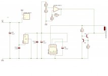
Here goes a preliminary diagram, I hope I'm interpreting you well!
We go for the two NPN CS then... parts size is actually almost the same and easy to find. I adapted the CS to draw only 5mA though, for the 10x DAC experiment.
I've been wondering if the circuit will also perform well with headphones of a lower impedance. Say typical 32ohm earplugs... since their voltage and current draw will have another midpoint. Also, according to my maths the lower the impedance the higher the current draw (at a lower voltage).
Attachments
A few corrections to make:
T20 is upside down (emitter/collector reversed)
R267 - bias resistor - too low value (suggest 10k) and needs to terminate on +5V (DAC supply) not Iout.
T19 collector goes to Iout
Headphone common (GND) goes to opamp output.
R266 - delete
R263 - turn into a wire (i.e. run opamp at unity gain)
R258 - becomes 5k6
You can still use 1.75V as the mid-point with lower impedance HPs.
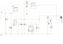
Looking much closer now. Just one wire missing - DAC Iout (L or R, pin6 or pin8) goes to T19 collector.
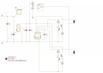
That's it 🙂
By the way, the selection of the opamp needs to pay attention to the common-mode input and output voltage range. A low-voltage opamp most likely will be fine but a normal +/-18V one may not.
By the way, the selection of the opamp needs to pay attention to the common-mode input and output voltage range. A low-voltage opamp most likely will be fine but a normal +/-18V one may not.
- Home
- Source & Line
- Digital Line Level
- Building a portable I2S 4x TDA1387 DAC