motor run caps are for Sissies

Hey...I thought motor run caps are "Approved by the Mighty ZM"(TM) ? 🙂
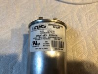
Out of curiosity, what uf and voltage rating are the motor run caps?
I've been using motor runs in my tube amps for some years now but I have shifted to Dc link film caps which are much smaller. Here is an example.
B32778P6506K000 EPCOS / TDK | Mouser
I have started to build my mofo but I am just going to use a couple of 19.5 volt Dell bricks.
ray
I've been using motor runs in my tube amps for some years now but I have shifted to Dc link film caps which are much smaller. Here is an example.
B32778P6506K000 EPCOS / TDK | Mouser
I have started to build my mofo but I am just going to use a couple of 19.5 volt Dell bricks.
ray
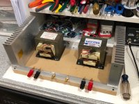
Nice work Flocchini! Looks tough as nails to me! 🙂
Nice one. Did you catch the whisper in "Babe I'm gonna leave you"? 😉
Gotta love Bohnam's squeaky pedal on "Since I've Been Lovin' You"
Nice one. Did you catch the whisper in "Babe I'm gonna leave you"? 😉
Hey...I thought motor run caps are "Approved by the Mighty ZM"(TM) ? 🙂
Thank you - ZM is who gave me the idea 😀
Out of curiosity, what uf and voltage rating are the motor run caps?
I've been using motor runs in my tube amps for some years now but I have shifted to Dc link film caps which are much smaller. Here is an example.
B32778P6506K000 EPCOS / TDK | Mouser
I have started to build my mofo but I am just going to use a couple of 19.5 volt Dell bricks.
ray
Like the size of what you are using 😉
Attachments
Nice work Flocchini! Looks tough as nails to me! 🙂
Nice one. Did you catch the whisper in "Babe I'm gonna leave you"? 😉
I need to find both pieces 🙂
IXYS and 159ZC
Today I finally had some time to do a few measurements. The results were different from what I had expected.
The source is a 600 ohm audio sine generator. It can output 2 VRMS. I used my normal 6N6P SRPP preamp for the gain. The gain is 8.5. So in theory I can output 17VRMS. According to my scope, this combo indeed does this.
The output impedance of this preamp is pretty close to 1K (measured). -3dB is around 130kHz. It was a lot higher, but the 6N6P tubes kept receiving radio Moskow, so I increased the grid stoppers.
The powersupply delivers 23V. I biased the Ixys around 2.3A and the IR part at 1.8A.
I've the option to switch between two fets. One is the classic IRFP250, the other one a big IXFK44N50. A 500 Watt Fet with a CISS of 8000pF. This high capacitance in combination with the high output impedance of the preamp should limit the bandwidth big time. But it doesn't.
Full load the -3dB is at 53 kHz. Not bad. With low loads (1VRMS) this goes up to 100 kHz. The IRFP250 doesn't do much better.
So my conclusions: the IXFK44N50 has a way lower CISS than on the datasheet mentioned. And a 1K preamp has no issues driving it.
Part two will describe the lower end of the power bandwidth.
Part 2, the Hammond
For my test, I cranked up the current. The Hammond 159ZC is rated at 2A.
The first tests I ran with 1.8A. With a 8ohm load, I get 12 Watts. Limited by the current.
Increasing the current to 2.3A increased the power to almost 20 Watts. Not to bad.
I even increased it to 3A, but this didn't do much. The output is now limited by the powersupply voltage.
With the Ixys at 2.3A, I'm getting a very clean 17W (no distortion visible on the scope: output is input sine). The sine starts to clip at 20 Watts. With the 3A bias, the clean sine stays at 17W. Only the clipping is higher (25 Watts). Maybe the choke itself is saturated.
The bandwith at the lower end is 14Hz (-3dB). With a low output (1VRMS), this is around 5 Hz. All measured before the output cap. My cap is only 3.5mF. This limits the lower end a bit (low power -3dB is 8 Hz in stead of 5 Hz).
The Hammond 159ZC is a capable choke. Using 2.3A is no issue as expected. This small choke can easily deliver close to 20 Watts.
Last edited:
Thanks for the measurement Ralph G. The Hammond 159ZC does indeed look like a perfectly capable choke for this application. Can you do some FFT's? I have a feeling the distortion might be quite high at 20w.
Thanks for the measurement Ralph G. The Hammond 159ZC does indeed look like a perfectly capable choke for this application. Can you do some FFT's? I have a feeling the distortion might be quite high at 20w.
I don't have a spectrum analyzer (yet 🙄). I only have a couple of DMM's (one nice one) and an old Kenwood Trio scope. For judging a signal I either overlay input and output signal or I look at the negative ADD.
In a classic overlay, you can see a difference very easily (line gets fatter). With the negative add (and scaled output), you should see a straight line. If not: distortion.
Or even faster: XY plot. Especially at higher frequencies this works perfectly.
But I can't tell what kind of distorting it has.
The 159ZC is rated at 2A with 60 mH. This is close to 2.5A and 50mH (my guess). Using the choke with the 2.3A I've chosen, should be well within the distortion free area.
The 193V can deliver much more (at lower frequencies). But used with only 24volts it won't deliver much more power at 8 ohms.
Upper limit value for C1?
Is there a upper limit for C1?
I am currently using 4.7uF but was thinking of adding ZM's favorite bypass - Phillips 1uF MKC
Thanks
Bob
Is there a upper limit for C1?
I am currently using 4.7uF but was thinking of adding ZM's favorite bypass - Phillips 1uF MKC
Thanks
Bob
...Increasing the current to 2.3A increased the power to almost 20 Watts.....
Ideal bias is very nearly V/R, where V is supply and R is all the resistance.
Taking exact 8 Ohm load, a part-Ohm in the choke, an Ohm in the MOSFET, say 10 Ohms.
For a 23V supply, indeed you want to be right around 2.3 Amps. Less will current-clip. More just increases losses in choke and FET.
That's for exact 8 Ohm load. Real loudspeakers will vary a bit down and a lot up. We don't really have to account for the up-swing of impedance, the speaker designer already figured that. Conventional full-range speakers won't have deep dips. Simple easy crossovers mostly don't give deep dips. Some elaborate crossovers are designed assuming "infinite" available current, which is true of many transistor amps, but not this one.
I suspect many users will be very happy biasing anywhere near V/R, taking R a little higher than speaker nominal impedance.
Of course within power needs/expectations. If you run 200W amps with lights blinking, 17-20 Watts will be less.
plan to build the mofo with 220v 1000w light bulb
bis 1A psu 20v output voltage 10v
will this configuration sound worse and have higher distortion than the choke version?
I don't need power, 1w is plenty for my compression drivers
bis 1A psu 20v output voltage 10v
will this configuration sound worse and have higher distortion than the choke version?
I don't need power, 1w is plenty for my compression drivers
You need a bigger PSU. 19v 2.65amp laptop smps are everywhere. MOSFETs have 4.5v drop so your 10v supply gives 5.5vpp. That’s about 0.48wrms max. Kind of wimpy. And distortion with lightbulb is much worse than choke. A 19v 4.6amp is even better.
Last edited:
Which could actually sound better, especially on widebanders and compression drivers. Build it and listen, try reversing speaker connection an listen again. You are in for a surprise.. . . And distortion with lightbulb is much worse than choke. . . .
Continuing, here is the revised layout that follows UMS guidelines (80 mm x 40mm mounting holes and Mosfet mounting at 15mm away from mounting hole.) Also included cap pitch options for C1.
regards
Prasi
Hi Prasi,
Nice layout. I think UMS says mosfet mounting hole is 20mm away from PCB mounting hole.
https://cdn.shopify.com/s/files/1/1006/5046/files/universal-mounting-specification-v2.1.pdf
If you have the time or inclination, if possible, I would suggest making one with a Juma cap Mx on same board, using underhung MOSFETs directly underneath board and clamped by screws through PCB. Then avoid separate PCB screws altogether. The two MOSFETs would sit on ends left and right at 80mm spacing which fits on 100mm long by 50mm(or up to 100mm to have room for caps) PCB, add two 22mF 25v caps (35mm dia, 10mm pitch snap in) and 3W axial 0.47R (on +ve and -ve or GND sides) for CRC between the cap Mx and the MoFo. This will allow use of 24v smps to get 20v Vcc and very low noise as I have measured. It’s so quiet it can be used as a headphone amp even.
Thanks for your efforts here.
Happy Holidays / xmas!
Cheers,
X
X
Last edited:
Yes psu is laptop 19.5v 120w
Bias is 1A to reach 10v at the output before cap
I could halve the load resistor (2000w bulb) to bias at 2A
Reversing the polarity affect the sound?
Speakers are jbl 2226 15inch and 2447 1.5 compression
Passive crossover.
Plan to go active biamping with 2 mofo per channel
Bias is 1A to reach 10v at the output before cap
I could halve the load resistor (2000w bulb) to bias at 2A
Reversing the polarity affect the sound?
Speakers are jbl 2226 15inch and 2447 1.5 compression
Passive crossover.
Plan to go active biamping with 2 mofo per channel
- Home
- Amplifiers
- Pass Labs
- Build This MoFo!