Hi res07njc,
You might look at something I did a while back here with LU1014D based on another member’s design.
MOSFET Source Follower Headamp
There are some similarities. Perhaps run a sim in LTspice first?
You might look at something I did a while back here with LU1014D based on another member’s design.
MOSFET Source Follower Headamp
There are some similarities. Perhaps run a sim in LTspice first?
Last edited:
xrk, I actually did read through that thread some time back, and it was responsible for causing me to dust off those LU fets.. then MR's MoFo came along... and well. I'm not so good at Spice, but it's not a complicated schematic and would probably serve me well to try it out before buying some specific parts.
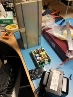
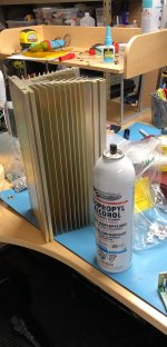
I've been slowly gathering the parts for my Big MoFo build. 24v 250W (135W without forced air) SMPS from eBay, power module heatsink from eBay (I plan on getting it cut into 2 for monoblocks), and the Hammond 193V. I had a lot of other projects planned, but this one was just too simple (???) and fun to not get started on 🙂!
Attachments
LU1014 is rated 24V.
In this MoFo the swing can be twice the supply.
You can't run over 12V. For 8r load, aim at 1.5A. 18W dissipation. Ideal output 9W, probably 7W before distortion.
Biasing that VERY high gain JFET will be super tricky.
In this MoFo the swing can be twice the supply.
You can't run over 12V. For 8r load, aim at 1.5A. 18W dissipation. Ideal output 9W, probably 7W before distortion.
Biasing that VERY high gain JFET will be super tricky.
LU1014 is rated 24V.
Biasing that VERY high gain JFET will be super tricky.
Maybe use a zener over the trimpot. That way the mains fluctuations don't have as much influence.
I'm using the normal IRFP250 and I'm living in a country with a very, very stable mains. But even over here there is a bias difference between daytime and nighttime.
PRR.. I hadn't considered the Mofo voltage swing and limitations that poses for the LU part. I do happen to have a 12v/8a brick with no prior intended purpose, so I'll just use that instead. A happy coincidence.
Ralph.. there is another LU buffer schematic on the web (ironically with a choke loaded source.. it's all been done!) that does use zener in the bias scheme, so if all else fails I could try that. thanks for suggesting.
Ralph.. there is another LU buffer schematic on the web (ironically with a choke loaded source.. it's all been done!) that does use zener in the bias scheme, so if all else fails I could try that. thanks for suggesting.
boyz , MoFo or not , if you put cascode to serve as voltage umbrella for Lu , it's not so big possibility that Mosfet just decide suddenly to take day or two of vacation , leaving un-umbrelled sissy JFet
so , if you decide proper resistor values for cascode voltage level , and if you put capacitor across lower resistor in that voltage divider , what's that having with swing of amplifier ?
so , if you decide proper resistor values for cascode voltage level , and if you put capacitor across lower resistor in that voltage divider , what's that having with swing of amplifier ?
Seemed like a surprise to me. The schematic I vaguely referenced above(with choke) uses a 21+/-, but not having a full understanding of chokes and why Mofo is generating 2x supply volts... not in the position to argue. ok, so I'm back using the 19V bricks!
start separate thread , and we will help to make it ....... and you'll understand it
probably even more than I understand it

probably even more than I understand it

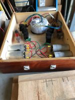
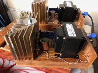
The MoFo is up and running
Used 15VAC transformer (500VA) to do CLC PSU
Bias is 2.5A (voltage with this is 18V)
Driving with XP-10
Very nice sound with great soundstage. Primarily female and male vocalists at this point. Will try some Led Zeppelin later 😀
Thank you, thank you and happy holidays
Attachments

View attachment 652376The MoFo is up and running
Used 15VAC transformer (500VA) to do CLC PSU
Bias is 2.5A (voltage with this is 18V)
Driving with XP-10
Very nice sound with great soundstage. Primarily female and male vocalists at this point. Will try some Led Zeppelin later 😀
Thank you, thank you and happy holidays
Red and black wires to the output terminals are not consistent between the two mono blocks ??
- Home
- Amplifiers
- Pass Labs
- Build This MoFo!