
I can hold my fingers on a front aluminum bar for a couple of seconds no problem.
So maybe my camera is overly pessimistic after all.
So maybe my camera is overly pessimistic after all.
I can hold my fingers on a front aluminum bar for a couple of seconds no problem.
So maybe my camera is overly pessimistic after all.
Infrared sensors/cameras are bad on aluminum....
Unless you put a piece of Kapton tape on it. Emissivity of Kapton is 0.90 vs 0.2 of Al. Actually, white masking tape works well too or even black PVC tape. They don’t do well when things get toasty though. Plus, Kapton uses silicone adhesive which leaves no residue.
I thought so as 22uF wouldn't seem to make a lot of sense. I think perhaps it's another example of our different understanding despite our shared language as to me mF is the same as uF.
Did you try your power supply without the CRC; in theory the cap multiplier alone should be sufficient shouldn't it?
Cheers anyway.
I am not using any special language. This is SI prefix notation but we lack the Greek “mu” so people use “u”.
Metric prefix - Wikipedia
22mF stands for milliFarad. 1000 x 1uF or 1000 x 1 micro is 1 milli. 1000 is 10^3 and 1 micro is 10^-6 or 10^-3(milli).
Pass DIY Addict
Joined 2000
Paid Member
Infrared sensors/cameras are bad on aluminum....
Especially on raw aluminum. Painted or anodized makes for a much more accurate read with non-contact thermometers.
Pass DIY Addict
Joined 2000
Paid Member
Wanted to keep heatsinks electrically isolated from mosfets, but maybe you'r right and I will get rid of thermal pads to knock down the mosfets temp a little, thank you!
Removing a thermal pad will make your mosfet up to 12c lower. I measured some of this a few months ago and posted the results here.
Using Nelson's quote that ZenMod posted, you should be able to do rough-but-close-enough estimate of temperatures. If you think your temps are high, drill some holes in that board beneath the finned area of your sinks to improve the airflow. Anodize will also increase thermal radiation, keeping things even cooler.
I hope you are enjoying them - they look great and will sound even better!
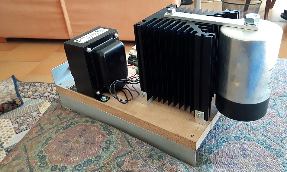
I would say that to make the air flow from the bottom upwards and facilitate the dissipation it can be enough to lift the heatsink like I did with aluminum supports
....different understanding despite our shared language as to me mF is the same as uF.....
Maybe an age thing. In my youth, "micro" was usually "m". And we had no "pico", we wrote "mmF". And an awful lot of 100,000 Ohm resistors were still "100M".
In the 1960s, US magazines found a μ for their type-case and began using it consistently. (However "letter u instead of μ is allowed by one of the ISO documents".) I think at that time our Euro friends were mocking our retro unit symbols.
It was much later that I began seeing "mFd" meaning MILLIfarads. BIG cap! I was not aware that we needed such a thing; there won't be that many 22,000μFd caps on one drawing, and it invites mis-reading because "m" for "μ" was not so far in the past. But one of the schematics programs uses one prefix-routine to normalize all user-entered values, and computers are our bosses, so we are stuck with it.
Pass DIY Addict
Joined 2000
Paid Member
Lifting the sink is the approach I used as well. Even a little will help - my spacer was about 1/4". Is that your output cap strapped to the sink? Or is it for the PSU?
Pass DIY Addict
Joined 2000
Paid Member
Interesting - what is the rating of your cap? Are you using a linear PSU or a switched mode? I'm gathering some big film caps for a tube amp PSU, never considered using them in a solid state amp...
I used a switching power supply. But I thought of integrating these large polypropylene caps that certainly helped the performance on the listening level and I also inserted a snubber. However I did not make comparisons with a classic linear PSU that I was about to make .... I have the material but.
References to these posts: here, here and here
References to these posts: here, here and here
Pass DIY Addict
Joined 2000
Paid Member
I have a 300mm version of the heat sink shown in the original article. Mrs JRKO is not enamoured of the idea of monoblocks. I’m planning on can cooling from the bottom of the heat sink. Where should I place the irf250’s?
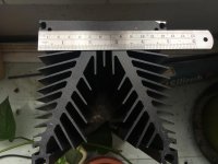

On close inspection of my amplifiers it turned out that the aluminum bars I made are too thin and unable to fully clamp the mosfets against the heatsink.
I remade the clamps from 6mm hard aluminum alloy and now both mosfets stay at 57-59C.
So extra care should be taken to ensure the proper bracing of the mosfets.
I remade the clamps from 6mm hard aluminum alloy and now both mosfets stay at 57-59C.
So extra care should be taken to ensure the proper bracing of the mosfets.
- Home
- Amplifiers
- Pass Labs
- Build This MoFo!