Question from the back of the class.
In the original article the author talks about biassing the MoFo at 2.5A compared to the original build of 1.7A and states that the distortion halves.
When you look at his distortion curves, for the 1.7A example, the distortion rises above 1% at around 12W. For the 2.5A example, a similar distortion is reached at say 21W.
But if you don't need these power levels, might there be a case for running with as high an Idss as possible for the installed heatsink capacity? Can you hear a difference between 0.5 and 1% THD? Or am I mistaken and there would be sonic improvements (differences) at higher currents, (I'm recalling my preference with with 6SN7s when run much closer to their operational limits)?.
Or is there some other consideration and the relationship between the supply voltage and current in achieving an optimum balance?
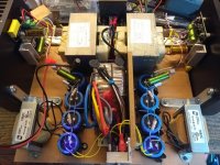
Attached is my current MoFo with MOTs and CLC power supply running at around 20V and 1.7A. Next up is trying different film and bypass caps.
In the original article the author talks about biassing the MoFo at 2.5A compared to the original build of 1.7A and states that the distortion halves.
When you look at his distortion curves, for the 1.7A example, the distortion rises above 1% at around 12W. For the 2.5A example, a similar distortion is reached at say 21W.
But if you don't need these power levels, might there be a case for running with as high an Idss as possible for the installed heatsink capacity? Can you hear a difference between 0.5 and 1% THD? Or am I mistaken and there would be sonic improvements (differences) at higher currents, (I'm recalling my preference with with 6SN7s when run much closer to their operational limits)?.
Or is there some other consideration and the relationship between the supply voltage and current in achieving an optimum balance?
Attached is my current MoFo with MOTs and CLC power supply running at around 20V and 1.7A. Next up is trying different film and bypass caps.
Attachments
Pass DIY Addict
Joined 2000
Paid Member
I haven't done any comparisons of the amp at different bias levels, so I don't have first hand experience here. You question does, though, remind me of a quote from Nelson about class-A amps and bias levels. Something to the effect of the output transistors continue to sound better as your increase the bias, right up to the point where they catch fire... On a more practical note, there is a point, for each voltage level, where increasing the bias does not yield more output power, only more heat (and better sound as Nelson indicated). I don't have a formula here, but I'm sure someone else can shed some insight on ratios of rail voltage to bias levels and output loads of 4-ohms or 8-ohms.
The general rule is that power output into 8-ohm loads is limited more by voltage, whereas power output into 4-ohm loads is limited more by bias current. Each has a limit, beyond which you're just making heat.
I think for each person, its a combination of how much power do you need, how much heat can you tolerate, how much heat can your sinks tolerate, etc.
Last edited:
In fig. 4 in the MoFo manual the curves are showed for the IRFP250 in the special configuration with 100% NFB (triode curves). If higher bias always gives lower distortion then the curves most be more and more linear? …..is this a general rule so it is not necessary to try to find a "hot spot" where curves are most linear but just try to get as high bias as possible?
65c transistor pin2 and/or 55c heatsink.
That’s hot enough that if you press your hand to it you’ll want to pull it off in less than 2 seconds.
That’s hot enough that if you press your hand to it you’ll want to pull it off in less than 2 seconds.
Proper FAB temperature ratings...
"The Aleph-X" thread Post # 1858
Just checked the Aleph X builders thread. I don't think 1858 is the correct post?
Thread is called "The Aleph-X"
Post #1858
Post #1858
Well let's see if your temperature calibration nomenclature
matches mine:
Blimey hot is 10 seconds hands on = 45 deg C.
Crikey hot is 5 seconds = 50 deg C.
Bloody hot is 2 seconds = 55 deg C.
X*?@! is 60 deg C.
All of these are within an acceptable range, although
X*?@! is resrved for the more mature constructor.
My personal experience: (Post #1669) with the bias set a 2.3A instead of 2.5A, the bass is very marginally less extended, but still tight and overall balance is still maintained.
Question from the back of the class.
In the original article the author talks about biassing the MoFo at 2.5A compared to the original build of 1.7A and states that the distortion halves.
When you look at his distortion curves, for the 1.7A example, the distortion rises above 1% at around 12W. For the 2.5A example, a similar distortion is reached at say 21W.
But if you don't need these power levels, might there be a case for running with as high an Idss as possible for the installed heatsink capacity? Can you hear a difference between 0.5 and 1% THD? Or am I mistaken and there would be sonic improvements (differences) at higher currents, (I'm recalling my preference with with 6SN7s when run much closer to their operational limits)?.
Or is there some other consideration and the relationship between the supply voltage and current in achieving an optimum balance?
Attached is my current MoFo with MOTs and CLC power supply running at around 20V and 1.7A. Next up is trying different film and bypass caps.
Pass DIY Addict
Joined 2000
Paid Member
Just measured the temp on mine again - running at 19v and 3A bias results in about 57w going into each sink with a temp of ~53c (~31c rise over ambient). The fet measures about 1c higher than the sink. The output fet is directly mounted on the sink with nothing more than thermal paste - each fet has its own sink. Mounting the mosfet without an electrical insulator needs a bit a caution as it makes the sink live - I'm using a wooden chassis. No problems with heat or the mosfet after a few months of this configuration.
I am seeing a 10 c difference between the face of the heatsink where the transistor is mounted and the fins of the heatsink. 55c on the fins and 65 c on the face. I immediately backed it down.
Question from the back of the class...., might there be a case for running with as high an Idss as possible.....
Yes.
Increasing standing current much above load current is one of the several ways to reduce THD.
For best use of costly power (and sink) you might bias at 16V 2 Amps, then swing up to 4 Amps and down to zero Amps.
How do you do this? Transconductance, Gm. A change of charge (voltage) on the control terminal (Gate-Source) causes a change of current in the output circuit (Drain-Source).
Is Gm constant? A little thought shows that Gm must go to zero at zero current. And there is no "wake-up point" where it suddenly snaps to a specific value. And the few MOSFET data which plot Gm show it varying very significantly with current.
Worked common-Source the THD may rise past 10% just before clipping. The MoFo works as Source-follower which masks much of the change of Gm, but may still rise past 0.1% before clipping.
OK, go to excess. Instead of 2 Amps, let us run 200 Amps (and 100X the heat and electric bill). Now instead of 2A +/-2A, approaching a swing of zero to 4 Amps, we have a swing of 198A to 202A (200A +/-2A) and the variation of Gm is probably 100 times less, THD may be 100 times smaller.
The higher current will require a MUCH larger choke. Nominally 100X the weight. Actually an iron core choke also distorts (this may be part of MoFo's THD) and the smaller *swing* may distort less. So maybe it won't be 100X. Still your UPS man will scowl.
There are several causes of distortion beyond change of Gm with current. Voltage effects from plate to grid (Drain to Gate). MOSFETs in particular show (inevitably) large change of capacitance with voltage and this can be seen in some of Mr Pass' simplest designs as a rise of THD in the top of the audio band.
Note that this is for choke(transformer) loaded. Resistor-loaded, seen in another thread, gets much less advantage because the DC feed resistor is still an AC load. But the main folly is that R-loaded amplifiers are SO inefficient that we can rarely afford to go generous, at least at speaker levels.
Push-pull (not choke-loaded) class A offers other THD techniques which are cleverer. To some degree high current "is good" but much depends on the details.
a resistor loaded buffer suffers less from Gm change? Does it need high Gm?
I plan to use resistor loaded buffer for mid-tweeter, 1w power, 1A bias, Gm should be round 3 the mosfet is BUK7575-55, Vds=3v Ciss=400pf
Is the low standby Vds a problem? I swing only 2V RMS from the DAC
IRFP140 seems to have Gm=3 at 2A bias, difficult to determine on the datashet graphs. It climbs to 10 only at 12A
a resistor loaded buffer suffers less from Gm change?..
That is not what I said. The question was about running "extra" current to reduce THD. With an ideal choke, this is effective. Even a real choke shows improvement. But resistor loaded, a large current is either a smaller resistor or much higher dissipation.
New YARRA integrated preamp suitable for MoFo here:
The YARRA Preamplifier/HPA for Melbourne DB Group Buy
The YARRA Preamplifier/HPA for Melbourne DB Group Buy
Ok, I'm deciding if I would build the MoFo.
Most of it is pretty reasonable for cost and build, but finding good heatsinks for it is hard to find good economical versions here in AU.
Seen two good versions so far:
Oxidized black Pass high-power class A amplifier heatsink radiator 260*150*75mm | eBay
China via ebay - Oxidized black Pass high-power class A amplifier heatsink radiator 260*150*75mm 2.4kg and about AU$93 each including freight
https://au.element14.com/aavid-thermalloy/db120-20/heat-sink-t-slots-0-41-c-w/dp/179955
Element14 DB120-20 - Heat Sink, Square, 80mm, 0.41 °C/W, 125 mm, 135 mm, 120 mm 2.1kg AU$89 each including free freight
The cost of the heatsinks are nearly 50% of the other parts. The weight of them make it cost to import them from US or China etc.
Are there any other type or supplier heatsinks that are good and more reasonable costs for AU?
- Home
- Amplifiers
- Pass Labs
- Build This MoFo!