janneman said:Syn08,
I have two queries, one OnT, one OffT:
OnT:
After Edmonds question I looked for a model for the 1166, but didn't find one. Your reverse engineered model looks quite detailed, how did you arrive at it?
OffT:
I am curious why you chose your particular domain name. Having read a lot about synaestesia lately, it jumped out to me. Care to enlighten me?
Jan Didden
1. Don't ask, don't tell. 😀
2. This was my daughter's (now at age of 20) domain I registered for her in her early teen. She's not using it anymore so I took it over for the benefit of the DIY audio community and my own fun. Also, syn08 was her Internet identity that I took over as well 😀
syn08 said:
1. Don't ask, don't tell. 😀
2. This was my daughter's (now at age of 20) domain I registered for her in her early teen. She's not using it anymore so I took it over for the benefit of the DIY audio community and my own fun. Also, syn08 was her Internet identity that I took over as well 😀
OT/
Not wanting to be a pita, but why did you chose that particular domain name? If it is nomb, that ok too, of course.
Jan Didden
janneman said:
Not wanting to be a pita, but why did you chose that particular domain name? If it is nomb, that ok too, of course.
It was not me choosing the domain name. I'll ask her and let you know 😀
Re: Re: Re: Re: LT1166
Why? Anyhow, my simulations confirm the TC (at 27 deg. +3.1%/K).
I don't think it's a complexity vs. performance trade, rather a inherent property of the design concept.
You may wonder why I'm moaning about this TC? Simply, because I've recently designed a competing circuit, which is essentially faster, more flexible and regarding the number of trannies much simpler, although 3...4 times more expensive than a LT1166.
BUT... this circuit too has a TC of ~3%. So I ask myself how serious is this flaw?
One more remark on the LT1166: My sim reveals that, opposed to the data sheet, the product of drain currents is NOT constant. Instead, the OP devices are always kept 'on' by (softly) clamping the minimum drain current at about 1/4 of the nominal idle current.
Did you observed this too?
BTW1, my circuit does roughly the same, but one can choose the minimum Id at will (preferably at a lower value to limit the PD).
BTW2, the convergence problems are gone now. Thx again.
syn08 said:http://www.synaesthesia.ca/files/LT1166.PNG
I did not simulate at different temperatures, but I have good reasons to believe it will not model correctly the datasheet TC.
Why? Anyhow, my simulations confirm the TC (at 27 deg. +3.1%/K).
I don't think it's a complexity vs. performance trade, rather a inherent property of the design concept.
You may wonder why I'm moaning about this TC? Simply, because I've recently designed a competing circuit, which is essentially faster, more flexible and regarding the number of trannies much simpler, although 3...4 times more expensive than a LT1166.
BUT... this circuit too has a TC of ~3%. So I ask myself how serious is this flaw?
One more remark on the LT1166: My sim reveals that, opposed to the data sheet, the product of drain currents is NOT constant. Instead, the OP devices are always kept 'on' by (softly) clamping the minimum drain current at about 1/4 of the nominal idle current.
Did you observed this too?
BTW1, my circuit does roughly the same, but one can choose the minimum Id at will (preferably at a lower value to limit the PD).
BTW2, the convergence problems are gone now. Thx again.
YAP schematics and short description
http://www.diyaudio.com/forums/showthread.php?postid=1595560#post1595560
http://www.diyaudio.com/forums/showthread.php?postid=1595560#post1595560
Re: Re: Re: Re: Re: LT1166
- Klaus
Sounds interesting, Edmond. Do you plan to share this idea, sometime?Edmond Stuart said:Simply, because I've recently designed a competing circuit, which is essentially faster, more flexible and regarding the number of trannies much simpler, although 3...4 times more expensive than a LT1166.
[...]
Instead, the OP devices are always kept 'on' by (softly) clamping the minimum drain current at about 1/4 of the nominal idle current.
[...]
my circuit does roughly the same, but one can choose the minimum Id at will (preferably at a lower value to limit the PD
- Klaus
syn08 said:
It was not me choosing the domain name. I'll ask her and let you know 😀
I suppose it is about dreaming images when listening to the music. Also, it may be feeling goosebumps when hearing the sound.
🙂
Wavebourn said:
I suppose it is about dreaming images when listening to the music. Also, it may be feeling goosebumps when hearing the sound.
🙂
And not being able to stop tapping your feet when you hear music. And. And.
You know there are people with significant brain damage that don't know how to dress, or open a door, or brush their teeth, or any of those routine things we take for granted. Did you know that some of them CAN do all that as long as they SING what they want to do?
There is a school of thought that says that music is the source of all human culture, not the other way around.
Sorry for OT rant. But it's all so ******* interesting!
Jan Didden
janneman said:
And not being able to stop tapping your feet when you hear music. And. And.
You know there are people with significant brain damage that don't know how to dress, or open a door, or brush their teeth, or any of those routine things we take for granted. Did you know that some of them CAN do all that as long as they SING what they want to do?
There is a school of thought that says that music is the source of all human culture, not the other way around.
Sorry for OT rant. But it's all so ******* interesting!
When I read audiophile reviews the only word can explain what is written: synesthesia
However, sometimes it is intentionally well performed trance induction, but when audiophiles themselves explain what they hear it is definitely synesthesia.
Wavebourn said:
When I read audiophile reviews the only word can explain what is written: synesthesia
However, sometimes it is intentionally well performed trance induction, but when audiophiles themselves explain what they hear it is definitely synesthesia.
I don't think that there is ANY human perception or experience that is limited to only one single sense, in varying degrees.
Let someone trace a figure with their finger over your back. You can pretty well tell the shape of the figure. Why? You couldn't see it. Well, the touch signals also end up in your vision centers, and you can visualize the path of the finger and from that recognize the shape.
Neat, huh?
Jan Didden
Re: Re: Re: Re: Re: Re: LT1166
Hi Klaus,
Of course (opposed to JC), but not until I'm damn sure there are no caveats and so on (that means testing at different temperatures, currents, tolerances, etc.).
Regards,
Edmond.
KSTR said:Sounds interesting, Edmond. Do you plan to share this idea, sometime?
- Klaus
Hi Klaus,
Of course (opposed to JC), but not until I'm damn sure there are no caveats and so on (that means testing at different temperatures, currents, tolerances, etc.).
Regards,
Edmond.
LT1166
Interesting post, but it has nothing to do with the current topic.
syn08 said:
Interesting post, but it has nothing to do with the current topic.
Re: LT1166
It would be interesting to find out why is the LT1166 bias IC on topic (negative feedback) and an announcement about my new amp thread isn't.
Edmond Stuart said:
Interesting post, but it has nothing to do with the current topic.
It would be interesting to find out why is the LT1166 bias IC on topic (negative feedback) and an announcement about my new amp thread isn't.
Re: Re: LT1166
I put the LT1166 topic here because I (erroneously) thought it was discussed on this thread before. Although it was actually on another thread (Error Correction) it has all to do with NFB (i.e. based on massive NFB)
So, instead of redirecting the current topic to your own project, would you be so kind to answer my question: Did you also observed (by means of real measurements or simulations) that this chip behaves totally different as described in the data sheet?
syn08 said:It would be interesting to find out why is the LT1166 bias IC on topic (negative feedback) and an announcement about my new amp thread isn't.
I put the LT1166 topic here because I (erroneously) thought it was discussed on this thread before. Although it was actually on another thread (Error Correction) it has all to do with NFB (i.e. based on massive NFB)
So, instead of redirecting the current topic to your own project, would you be so kind to answer my question: Did you also observed (by means of real measurements or simulations) that this chip behaves totally different as described in the data sheet?
Re: LT1166
My question was: "Did you observe this too:
.... My sim reveals that, opposed to the data sheet, the product of drain currents is NOT constant. Instead, the OP devices are always kept 'on' by (softly) clamping the minimum drain current at about 1/4 of the nominal idle current."
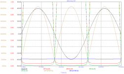
To make my point more clear I have simulated two test circuits, one with your model and one with a so called "NFI function source", i.e. a controlled current source that keeps the product of Id-N and Id-P at a constant level, that is, 150mA*50mA=0.0225 mA^2. Furthermore the tests circuits comprise a single 2SJ201/2SK1503 pair. RL= 8 Ohm, Vout = 40Vpk and Iq = 150mA.
As one can see, during near turn-off, the drain current is held at a more or less constant level, about 35mA (red curves). Consequently, the Id product is far from constant (brown curve), ranging from 0.0225 to 0.185.
The curves from the second circuit shows what you would get if the LT1166 would behave as described in the data sheet. Now Id drops to a minimum level of about 5mA (green curves) and the Id product is (of course) really constant (blue curve).
Please, notice that I'm NOT suggesting that the model (or even the chip itself) is wrong, I'm only surprised about the discrepancy between your model and the verbal part of explanation in the data sheet. The schematics however, are in agreement with your model circuit. So I concluded that your model is okay (at least regarding DC and AF).
Originally posted elsewhere by syn08
.........
I'm not sure I understand your question about the LT1166, could you clarify what is the behaviour you noticed?
My question was: "Did you observe this too:
.... My sim reveals that, opposed to the data sheet, the product of drain currents is NOT constant. Instead, the OP devices are always kept 'on' by (softly) clamping the minimum drain current at about 1/4 of the nominal idle current."
To make my point more clear I have simulated two test circuits, one with your model and one with a so called "NFI function source", i.e. a controlled current source that keeps the product of Id-N and Id-P at a constant level, that is, 150mA*50mA=0.0225 mA^2. Furthermore the tests circuits comprise a single 2SJ201/2SK1503 pair. RL= 8 Ohm, Vout = 40Vpk and Iq = 150mA.
As one can see, during near turn-off, the drain current is held at a more or less constant level, about 35mA (red curves). Consequently, the Id product is far from constant (brown curve), ranging from 0.0225 to 0.185.
The curves from the second circuit shows what you would get if the LT1166 would behave as described in the data sheet. Now Id drops to a minimum level of about 5mA (green curves) and the Id product is (of course) really constant (blue curve).
Please, notice that I'm NOT suggesting that the model (or even the chip itself) is wrong, I'm only surprised about the discrepancy between your model and the verbal part of explanation in the data sheet. The schematics however, are in agreement with your model circuit. So I concluded that your model is okay (at least regarding DC and AF).
Attachments
Re: Re: Re: Re: Re: Re: LT1166
As a kind of pre-view, you might have a look at my old auto-bias article: http://home.tiscali.nl/data.odyssey/AutoBias.html
My new circuit is based on the same 'bias sensor' as described in that article, however no isolator neither an integrator. Furthermore, the new 'bias sensor' (THAT300) also comprises its complementary counterpart (THAT320). Now the 33k resistors can be directly connected to the plus and minus power rails and the bootstrapping stuff (R3,C10) can be omitted (hint: the sum of reference currents is constant).
Regards,
Edmond.
KSTR said:Sounds interesting, Edmond. Do you plan to share this idea, sometime?
- Klaus
As a kind of pre-view, you might have a look at my old auto-bias article: http://home.tiscali.nl/data.odyssey/AutoBias.html
My new circuit is based on the same 'bias sensor' as described in that article, however no isolator neither an integrator. Furthermore, the new 'bias sensor' (THAT300) also comprises its complementary counterpart (THAT320). Now the 33k resistors can be directly connected to the plus and minus power rails and the bootstrapping stuff (R3,C10) can be omitted (hint: the sum of reference currents is constant).
Regards,
Edmond.
Re: Re: LT1166
Honestly, I did not go into this level of detail with the little LT1166, therefore, I am still having trouble following your description.
Can you clearly identify which curves are for the LT1166 and which are for the ideal model you created?
Edmond Stuart said:
My question was: "Did you observe this too:
.... My sim reveals that, opposed to the data sheet, the product of drain currents is NOT constant. Instead, the OP devices are always kept 'on' by (softly) clamping the minimum drain current at about 1/4 of the nominal idle current."
To make my point more clear I have simulated two test circuits, one with your model and one with a so called "NFI function source", i.e. a controlled current source that keeps the product of Id-N and Id-P at a constant level, that is, 150mA*50mA=0.0225 mA^2. Furthermore the tests circuits comprise a single 2SJ201/2SK1503 pair. RL= 8 Ohm, Vout = 40Vpk and Iq = 150mA.
As one can see, during near turn-off, the drain current is held at a more or less constant level, about 35mA (red curves). Consequently, the Id product is far from constant (brown curve), ranging from 0.0225 to 0.185.
The curves from the second circuit shows what you would get if the LT1166 would behave as described in the data sheet. Now Id drops to a minimum level of about 5mA (green curves) and the Id product is (of course) really constant (blue curve).
Please, notice that I'm NOT suggesting that the model (or even the chip itself) is wrong, I'm only surprised about the discrepancy between your model and the verbal part of explanation in the data sheet. The schematics however, are in agreement with your model circuit. So I concluded that your model is okay (at least regarding DC and AF).
Honestly, I did not go into this level of detail with the little LT1166, therefore, I am still having trouble following your description.
Can you clearly identify which curves are for the LT1166 and which are for the ideal model you created?
The red and brown curves are for the LT1166.
The green and blue curves are for the ideal model.
The black one is output voltage.
The green and blue curves are for the ideal model.
The black one is output voltage.
Edmond Stuart said:The red and brown curves are for the LT1166.
The green and blue curves are for the ideal model.
The black one is output voltage.
Isn't this a frequency effect? That is, have you added the 1uF caps to the LT1166 schematic?
Anyway, in using LT1166 I have not noticed or otherwise encountered this effect.
LT1166
Nope, it's not a frequency effect and of course I did not add a cap. Besides, as you can see, the test frequency is quite low: 20Hz. So a frequency effect is most unlikely.
As for the much higher Id levels at near turn-off (i.e. 35mA vs. 5mA), didn't you notice that effect or didn't you simulate or measure it at all?
- Home
- Amplifiers
- Solid State
- Bob Cordell Interview: Negative Feedback