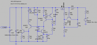
As I mentioned before, the main two components that predictably will make the circuit to oscillate are C1 and C2. Anything larger than 3nH will make it oscillate for me. Now, since I'm talking about the output cap and the upper resistor cap (in the divider for the base of Q3), it will be difficult to get low ESL values. That is my concern.
If anyone would like to try the exact circuit that oscillates for me, the attached zip file should contain all that is needed. LTSpice is freely downloadable from Linear Technology
http://ltspice.linear.com/software/LTspiceIV.exe
Installation is a breeze. The zip file should be unzipped in a directory named:
[wherever_you_installed_ltspice]\lib\sub\mylibs\
which in my case happens to be
c:\Program Files\LTC\LTspiceIV\lib\sub\mylibs\
After installing LTSpice simply open the file reg-toole10a.asc which will be in that directory. Then click on the "running man" icon to run the simulation. However, it would be good to set the solver to Alternate in the menu Simulate->Control Panel->SPICE, to get most accurate results.
Attachments
Here's a thought; I am questioning C1, the cap on the upper resistor on the base of Q3, becomes a bypass of all high freq ripple that happens to be on Vout. This bypasses all that ripple directly into the base of Q3. So I propose to either use a resistor (maybe 1kOHm) in series with C1, or not use C1 at all.
I still think there is something wrong with your simulation? I built the exact version that you are simulating on a PCB - I posted a picture some pages earlier - and it does not oscillate in real life, run from my normal lab power supply.
I am questioning C1
This is a standard method of increasing the loop gain for AC and thus increasing regulation. If the circuit is not stable with this cap then the whole circuit will have a problem.
MRupp said:I still think there is something wrong with your simulation? I built the exact version that you are simulating on a PCB - I posted a picture some pages earlier - and it does not oscillate in real life, run from my normal lab power supply.
Quite possible of course, these models can be far from real life in many respects.
Martin, I took the liberty to make the following changes, which IMHO are not outrageous. Set the load to SINE(75m 15m 1k5), the voltage source to SINE(30 15m 120), the ESL of C21 to 8nH, and the trans command to .tran 0 1.25 0 0.01ms startup uic.
See attached image pls.
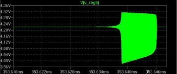
Perhaps in reality none of these appear in the real circuit. It still doesn't make me feel very good. The second thing that is worrying me a bit is the transient response (with that little bit of ringing) to abrupt changes in the load current.
See attached image pls.
Perhaps in reality none of these appear in the real circuit. It still doesn't make me feel very good. The second thing that is worrying me a bit is the transient response (with that little bit of ringing) to abrupt changes in the load current.
Attachments
Perhaps in reality none of these appear in the real circuit. It still doesn't make me feel very good. The second thing that is worrying me a bit is the transient response (with that little bit of ringing) to abrupt changes in the load current.
Need to check in the evening when I have access to LTSpice, to better understand what you are doing. Re. load changes, you need to see that they are in the audio frequency range. If your load is creating big step changes at higher frequencies, it is in itself instable and off course it will cause follow on proplems.
I am not saying that we do not have problems with the design, but we need to compare to some other regulators, to see how they would fare under the same conditions. That would better tell us if there is something wrong with the current design. I had the idea of trying a differential regulator, probably Borbely's design (I would not have all values exactly the same but the circuit should at least be working).
MRupp said:If your load is creating big step changes at higher frequencies, it is in itself instable and off course it will cause follow on problems.
A device that creates big HF step changes does not have to be unstable - it just has to be very fast.
An example of when this is necessary is a buffer / filter circuit on the o/p of the DAC that can deal with the HF noise without getting distressed.
It is not uncommon that such an amp could be functional & stable up to 100 Mhz.
Obviously if this cct oscillates it is a non starter but from what I know about the "sound" of power supplies we have to aim at having almost no ringing on transient response otherwise I would not expect it to sound good.
Did not get round to answer earlier. I generally agree with you, if the circuit oscillates it is a no no. Also, it should cope with all transients that there are (I am not so familiar with digital circuits and cannot readily assess what to expect there). And yes, I am aware that some people prefer low feedback regulators on the grounds that they should sound better, though I cannot report from my own experience.
My points are: I have not seen sufficient proof that this circuit is more unstable compared to other high feedback regulators. I am aware that they can be easily upset. So I would like to investigate just a little further until deriving at a conclusion. Lastly, the circuit (and it's variations) is simple enough to build on a single sided PCB and I still want to build versions when I find the time and test them (I am finishing up a MC phono stage and that will be the first place to use them, even if I replace them with something else afterwards).
Martin,
Thanks for your efforts and good luck with your prototype. I'm off to a mangrove swamp for two weeks. I expect no Internet access and real bugs. I'm looking forward to reading the results of your tests when I get back.
Jim
Thanks for your efforts and good luck with your prototype. I'm off to a mangrove swamp for two weeks. I expect no Internet access and real bugs. I'm looking forward to reading the results of your tests when I get back.
Jim
I'm off to a mangrove swamp for two weeks.
Two weeks? If you could stay in that swamp just a little bit longer 😀
I am already spending an undue amount of time on this and I am not sure how quick I can progress or get to a conclusion (I am not set up to perform comprehensive tests, for instance). All others, any further ideas or comments ?
Martin, I took the liberty to make the following changes,
Ok, here is the LTSpice circuit, ESL 0f C21 is now 8nH, startup command is the same as yours, except that I let it run for 3 seconds. Check if I still need to alter anything:
Attachments
MRupp said:
My points are: I have not seen sufficient proof that this circuit is more unstable compared to other high feedback regulators.
I am aware that they can be easily upset. So I would like to investigate just a little further until deriving at a conclusion.
I look forward to hear your conclusions.
my conclusions so far are that it is just important to have dynamic low noise as it is to have static low noise if we want to have truly great sounding equipment.
cheers
mike
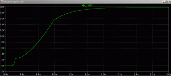
Here is the result I get, after ca. 2-3 secs the circuit has reached the set voltage of 20 Volts. I note also that in your chart, the oscillation occurs at 350 milliseconds, and the voltage is 4 Volts, but the circuit is set to 20 volts output. You still have me confused ... can you let the simulation run for, say 5 - 10 seconds then show oscillation at a steady state?
P.S. in the next couple of days I should have an alternative circuit (some Borbely shuntreg clone I hope) and will present it for test, then we should compare the two.
P.S. in the next couple of days I should have an alternative circuit (some Borbely shuntreg clone I hope) and will present it for test, then we should compare the two.
Attachments
I look forward to hear your conclusions.
I do not question that dynamic response is just as important, and that within the range of expected load or supply transients it should be stable, and I will give you MY conclusion, but would at the same time like to see some conclusions from others as well.
MRupp said:
... but we need to compare to some other regulators, to see how they would fare under the same conditions ...
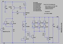
I agree. We could always compare against something very simple and with small parts count, like salas' shunt regulator, which happens to be an excellent performer in simulation as well as in real life. I am using it with my phono stage and it rocks. The attached image shows the circuit a bit tweaked by me to run higher current through the mosfet drivers. However, the circuit works very well even with just one jfet in that position and replacing the bd139 with bc550b.
Attachments
Hi,
try replacing the input CCS with a high voltage supply feeding a high resistance.
say 10kV through 63k giving a 159mA CCS.
Makes the simulation simpler and also finds whether it's the shunt that is oscillating or the CCS or an interaction between the two.
try replacing the input CCS with a high voltage supply feeding a high resistance.
say 10kV through 63k giving a 159mA CCS.
Makes the simulation simpler and also finds whether it's the shunt that is oscillating or the CCS or an interaction between the two.
like salas' shunt regulator, which happens to be an excellent performer in simulation as well as in real life.
I was looking at Salas' regulator with one eye but wasn't closely following it, and I must admit that I do not understand it yet, including some of the "design" decisions.
It would still leave for me the exercise to look at a "borbely" type of regulator because I am interested in this design, but the actual reason for doing it within this particular thread was to find out whether or not we have an issue with oscillations. And lastly, regarding sound, that may or may not be true, but this is just too dependent on individual taste and particular audio systems to be the main arbiter. I think everyone has to find that out for himself.
My 2 cents.
- Status
- Not open for further replies.
- Home
- Amplifiers
- Solid State
- Bipolar discrete shunt regulators