I finished testing the circuit from post 506. Attached is the circuit diagram that I used in my layout software. I used 3 LEDs as voltage reference for maximum flexibility, they can be bridged individually or replaced by a zener, depending on voltage requirements.
Also, I have miller caps for T3 (C6/C16) = 470pF and for T6 (C7/C17) = 1000pF. Only one cap is required in each position, the redundant caps in the layout software allowed me to have two different packages, one SDM cap (1206) and one leaded cap with 2,54 mm spacing. I finally decided on using the SMD caps (NP0 ceramics) as they need less space and can be placed closer to the transistor (less inductance).
The miller caps are required for stability as the circuit oscillates without them at some 20 - 30 MHz (setting R7 to 65 Ohms and R8 to some arbitrary 30 Ohms reduced those oscillations but did not eliminate them completely). With the caps I can only see a couple of millivolts of noise on my oscilloscope but my testsetup does not allow me to analyse this further.
Attachments
This is the final layout with components. The size is 61 mm x 44 mm. Originally it was 60 mm but I added C7/C17 to my already "completed" layout after I found that the CCS oscillates without them. My prototype has this cap still soldered accross the board, btw..
Attachments
Why is C5 connected to C3?
Should it be connected to the lower supply rail?
Could R12 be replaced with a Jfet or crd and get any improvement without any risk of oscillation?
Should it be connected to the lower supply rail?
Could R12 be replaced with a Jfet or crd and get any improvement without any risk of oscillation?
Why is C5 connected to C3? Should it be connected to the lower supply rail?
Good catch, it should either go to ground or from plus to the node between R2 and R12. 😱 In simulation it does not seem to change anything in terms of noise, PSRR, or load regulation, but still ...
Martin,
I like the extra holes to allow combinations of zeners and/or led's. I guessed at a few values and ran a simulation. Regulation, bandwidth and stability looked great. Even better your real test was good.
Thanks
Jim
I like the extra holes to allow combinations of zeners and/or led's. I guessed at a few values and ran a simulation. Regulation, bandwidth and stability looked great. Even better your real test was good.
Thanks
Jim
Hi Martin,
Any chance you could post the schematic please?
Jim, welcome back from swampland to "cold but sunny" land 🙂
Any chance you could post the schematic please?
Jim, welcome back from swampland to "cold but sunny" land 🙂
Any chance you could post the schematic please?
The circuit is in the zip file in post 567, which is basically the same circuit as in post 506, except that it now has an additional miller cap (C7) as described before.
Could R12 be replaced with a Jfet or crd and get any improvement without any risk of oscillation?
Actually no improvement can be seen - in simulation, performance just looks identical. I compared various configurations: my test version (C5 on C3), the "corrected" version (C5 to +), a CCS for R12, and finally no bootstrap at all, i.e. just one resistor instead of R2/R12 and C5. It appears that this is not a critical element and the bootstrap can be omitted.
Here is the PCB of the circuit from 567 (seen from the top, i.e. component side):
Attachments
Well, it certainly looks nice 😀 But I now need to complete my alephono clone to put the regulator to some good use. The time I spent on the regulator would just have been enough to completete the phono stage, so kind of a catch 22 situation now.
MRupp said:Well, it certainly looks nice 😀 But I now need to complete my alephono clone to put the regulator to some good use. The time I spent on the regulator would just have been enough to completete the phono stage, so kind of a catch 22 situation now.
Very nice, I'm glad it works now for you, I know how frustrating a new design can be. I've been designing/developing yet another shunt regulator and it's been a huge time sink.
I know how frustrating a new design can be.
It is not really frustrating - unless you swap the mosfet and the shunt BJT as I once did in a prototype - but costs a lot of time. And I hope you learned something new - I did.
You must have learned the right things. It simulates about 40dB better than the earliest version I looked at and the phase shift is about 200 degrees better, way into the stable area. I expect it will happily power my mistakes.
Jim
Jim
JimT said:You must have learned the right things. It simulates about 40dB better than the earliest version I looked at and the phase shift is about 200 degrees better, way into the stable area. I expect it will happily power my mistakes.
Jim
Jim, this improvement was over which version? The compensation caps if anything, would lower the performance slightly in the higher frequency.
Martin, of course, any change on some existing design, or a new design, is a learning experience. I do find it frustrating when the new thingy behaves too different than the simulation. But it's a good reminder that one should not read too much in a simulation result. I speak of course, only of my experience.
If i may ask
have we reached a version which is suitable for thr GB or do we wait for something?
Sorry if i can't provide any help, i'm still in the state of learning.
Greetings
difool
have we reached a version which is suitable for thr GB or do we wait for something?
Sorry if i can't provide any help, i'm still in the state of learning.
Greetings
difool
I just received some boards that I drew up based on the latest iteration of Colin's shuntreg design, and a simple CLC pre circuit. I'm looking for a few people to try these out and make comments on them and depending on the results, perhaps this GB might get resurrected 🙂 If you're interested, please contact me and we can work the details out. The more fancy the measurement equipment you have and willingness to get cracking on this, the better. I'm willing to ship worldwide and would like to recoup a tiny bit of my investment so far.
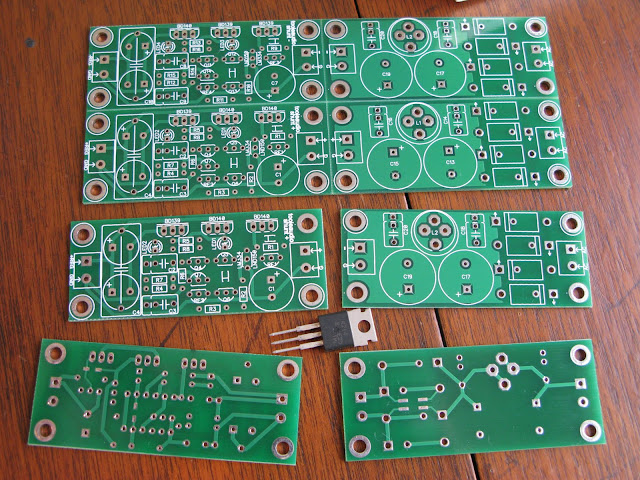
Bigger pic here:
http://picasaweb.google.com/lh/photo/JapdboKbRhH8U6q5Kr66Gw?feat=directlink
Bigger pic here:
http://picasaweb.google.com/lh/photo/JapdboKbRhH8U6q5Kr66Gw?feat=directlink
- Status
- Not open for further replies.
- Home
- Amplifiers
- Solid State
- Bipolar discrete shunt regulators