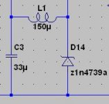
I believe I found the source of oscillation. By default I set all caps in my simulations to 1 ohm ESR and 15nH ESL. This, in conjunction with a smallish capacitance value for C3, leads to oscillation. Some playing around with values showed that increasing the capacitance value of C3, or decreasing ESL on C3, both tend to correlate positively with a lower chance of oscillation. Adding a small inductor between the zener and C3 (as shown in the attached image) decreases even more the chance of oscillation. In fact, in this attached image, C3's ESL was exageratedly set to 30nH, and the circuit was stable.
I suppose this may point out that both C3's parasitic ESL value and the layout in that PCB area are important?
I suppose this may point out that both C3's parasitic ESL value and the layout in that PCB area are important?
Attachments
This could be a dumb idea, but I thought I should look back at CToole's version of this. I found that he had a larger value for a resistor in the area I think is problematic. As I don't really know what I'm doing I just tried his value in the simulator. I changed R1 in the schematic in post #466 from 196 to 400 ohms. It is now stable. I tried it without a compensation cap and eliminated R8. It does twitch just a bit, but hopefully this helps.
Jim
Jim
Jim, setting ESL > 3nH on the output cap will make it oscillate even with a 400 ohm value for R1. I should add that I do not actually suggest that the inductor be used in between the zener and the cap; I merely mentioned that it had a positive effect. The circuit seems quite sensitive to the ESL value of almost all caps. How difficult it is in practice to achieve < 3nH inductance in a circuit? Or maybe it doesn't even matter in a real circuit?
Jan, thanks for the suggestion, I played quite a bit with R8, to no avail though.
Martin, before the alternate ccs idea came about, were you going to build a p-p version, or pcb? With a p-p it'd be very easy to test either of the ccs ideas, but if it oscillates I guess you'd be doubting the wiring? Even though home made pcbs are not out of the question for me, I still prefer point-to-point wiring for simple prototypes, especially because they're simpler to change. To each his own though.
After some more tweaking it seems that the main two factors in getting it to oscillate are the ESL value of C1 and C2. Anything over a few nH will do it. Didn't find a solution yet.
ikoflexer said:After some more tweaking it seems that the main two factors in getting it to oscillate are the ESL value of C1 and C2. Anything over a few nH will do it. Didn't find a solution yet.
Nice work. Adding the nH to the capacitors does some interesting things. My resistor change just seems to reduce the bandwidth and is probably not very predicable. I hope Martin has a good fast oscilloscope.
Jim
mikelm said:
do you mean small bjt & big mosfet ?
mike
Big mosfet as "master", fast BJT -"slave"
ikoflexer said:After some more tweaking it seems that the main two factors in getting it to oscillate are the ESL value of C1 and C2. Anything over a few nH will do it. Didn't find a solution yet.
Do you try damping series for C1&C2 resistor or/and stopper resistors for Q3 & Q1?
ikoflexer said:After some more tweaking it seems that the main two factors in getting it to oscillate are the ESL value of C1 and C2. Anything over a few nH will do it. Didn't find a solution yet.
Then you have a problem. In p2p as well as pcb layout you will have more than just a few nH.
The reason it stopped oscillating with the L between the cap and the zener is that that introduces some feedback to the reference for high frequencies, which lowers the gain, which of course raises Zout.
This is the everlasting trade-off. Unless you know exactly what you are doing with transfer function stuff and all that (and I'm not claiming I do!) the only safe route is to limit the loop gain to a safe value. R8 is a good point to do that. Also remember that if it is 'just' stable in your case, the other guy can have a wildly oscillating copy. What I would do for instance is find R8 where it stops oscillating and then double it. Or something like that.
Jan Didden
Uchi Deshi said:
Do you try damping series for C1&C2 resistor or/and stopper resistors for Q3 & Q1?
Yes, I tried both and did not fix it.
janneman said:
Then you have a problem. In p2p as well as pcb layout you will have more than just a few nH.
The reason it stopped oscillating with the L between the cap and the zener is that that introduces some feedback to the reference for high frequencies, which lowers the gain, which of course raises Zout.
This is the everlasting trade-off. Unless you know exactly what you are doing with transfer function stuff and all that (and I'm not claiming I do!) the only safe route is to limit the loop gain to a safe value. R8 is a good point to do that. Also remember that if it is 'just' stable in your case, the other guy can have a wildly oscillating copy. What I would do for instance is find R8 where it stops oscillating and then double it. Or something like that.
Jan Didden
Will try again with R8. Jan, I have a vague recollection that small caps (pico valued) are used to pass the high freq signal from the base of the driver transistor to ground, in case of oscillation. There is, of course, performance reduction at high frequency, but that is something one may have to live with to gain stability. Has anyone tried that? I'm a bit short of time at the moment.
You could try miller compensation as is often used in a power amp voltage gain stage. After all, this is very much like a power amp except with DC input.
A small cap from collector to base of the error gain transistor.
Jan Didden
A small cap from collector to base of the error gain transistor.
Jan Didden
I played a little with transient response, stepping the supply voltage by 1 Volt, ristetime 0.1 µsec., with the original circuit and then with the new current source and as expected I can get both of them to start ringing. Off course, I do not believe that we would normally see such large transients in the raw supply, but nevertheless, it seems to show potential issues.
This seems to work very well, so thanks for the tip. It does not completely eliminate the ringing but decreases it by several orders of magnitude. I initially tried the compensation cap on Q1 (original schematics) but moving it to the right transistor (Q3) works much better. I value between 100 - 220pF (3-6 nH) seems sufficient. Here is a picture of the remaining ringing, just a couple of mV and settles very quickly, and note that this is after a transient of 10V/µsec. ... green is the original CCS, blue is the new CCS, simulation with new IRF subcircuit which seems more realistic:
A small cap from collector to base of the error gain transistor.
This seems to work very well, so thanks for the tip. It does not completely eliminate the ringing but decreases it by several orders of magnitude. I initially tried the compensation cap on Q1 (original schematics) but moving it to the right transistor (Q3) works much better. I value between 100 - 220pF (3-6 nH) seems sufficient. Here is a picture of the remaining ringing, just a couple of mV and settles very quickly, and note that this is after a transient of 10V/µsec. ... green is the original CCS, blue is the new CCS, simulation with new IRF subcircuit which seems more realistic:
Attachments
Well I have given my humble opinion but we need others too in order to move ahead and finally get the GB going again if there are no further concerns here.
"Decisions, decisions ..." as Nelson Pass would say
 . My vote goes to the new CCS, it's performance at higher frequencies is not quite as good as the old one but still good enough. To me it looks just as stable, requires less parts, and is more scalable. This still leaves the question as to what to do with the actual regulator part. And we should still build a prototype again to be on the safe side.
P.S. I am attaching the subcircuit for IRF9610 that I was using, I found it on this forum, supplied by one Harry Haller. Methinks it is from the IRF library but since they divested this part I can no longer find it there:
Attachments
One less electrolytic in the shunt portion makes a large improvement. Perhaps removing the capacitor by the zener is an option. Christer did some nice work on noise in LED's and Zeners. Maybe LED's instead of zeners below 9.1 V and quiet zeners for higher voltages would be an option.
Jim
Jim
Incidentally, for those looking for spice models, here's a site with a bunch of libs. I believe pwrmos.lib will have the irf9610 among many others.
http://musatoffcv.narod.ru/Libs/Models.htm
http://musatoffcv.narod.ru/Libs/Models.htm
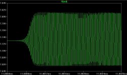
Martin, perhaps small differences in our simulations result in these effects. When I was talking about oscillation I was not talking about the simple ringing on the transient response, but full blown oscillation, such as seen in the attached image, generated by the original circuit with a 200p from C to B on Q3.
Attachments
One less electrolytic in the shunt portion makes a large improvement. Perhaps removing the capacitor by the zener is an option. Christer did some nice work on noise in LED's and Zeners. Maybe LED's instead of zeners below 9.1 V and quiet zeners for higher voltages would be an option.
Tim,
don't have much time right now. I looked into Christer's article and note that the noise of both higher voltage Zeners and a string of LEDs is in the same ballpark. The noise of either of them will be amplified by the error amplifier and determines, or rather limits, the noise performance of the regulator. Try a noise simulation with a 1µF cap over the audio range and you will see the pole in the noise level. Read also the section in Jung's article that I referenced earlier. So without a big cap across the voltage reference the regulator may be too noisy.
perhaps small differences in our simulations result in these effects. When I was talking about oscillation I was not talking about the simple ringing on the transient response, but full blown oscillation, such as seen in the attached image, generated by the original circuit with a 200p from C to B on Q3.
Yes, we need to find out why your simulations are oscillating and mine are not, very strange. I do use series inductance for all caps, maybe we have different values? A ballpark figure for a low ESL electrolytic cap should be some 6nH. I found this value in a datasheet for 100µF Rifa (axial) electrolytics that I have, similar in size to radial caps, this is what I used by default, for want of better data. Varying it a little does not change much, but it should be in that range. For the compensation caps I used 3nH and going too high with the inductance here will cause problems, too. Can you confirm what inductance values you are using?
Btw., this means we need to select appropriate compensation caps, such as small leaded NPOs or even SMT caps, close to the transistor.
Obviously if this cct oscillates it is a non starter but from what I know about the "sound" of power supplies we have to aim at having almost no ringing on transient response otherwise I would not expect it to sound good.
As a standalone regulator we do not know what kind of demands different applications will put on this cct and if that HF ringing is excited by sudden load variation I would expect the sound to be rough and unclear when compared with a regulator that does not ring.
Personally I would prefer a regulator with higher o/p impedance and more stability.
mike
For these simulations I have been using 15nH, 0.5ohm parasitic values, which may seem exagerated. Do you think it is practical to assume much smaller inductance?
For these simulations I have been using 15nH, 0.5ohm parasitic values, which may seem exagerated. Do you think it is practical to assume much smaller inductance?
I believe 15nH is fine for the electrolytic caps, but for the compensation cap this could be exactly the issue. I would need to do a few more tests but I believe I saw oscillation at or above 10nH, so either use no compensation cap or a cap with low inductance and close to the place where it compensates. I do not have more exact inductance values right now (other than that my 20mm long rifa cap has 6nH), but attached is an excerpt from an Epcos datasheet for ceramic caps, the graph on the left shows how the resonance frequency of a 1nF C0G cap (exactly what we need) is influenced by lead length and hence inductance:
Attachments
- Status
- Not open for further replies.
- Home
- Amplifiers
- Solid State
- Bipolar discrete shunt regulators