So i tried a lot of different's combination, using some of what was said here, and some with "trial & error" 🙂
The result is kind of much better now.
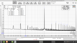
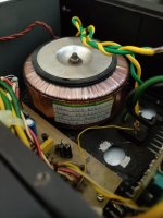
If i move the trafo away from the chassis, the 250, 350, 450Hz etc... dissapears.
So i turned it 180C, and moved it as long as possible away from the output terminals.
(I forgot to take a screenshot when trafo was moved aeay from chassis)
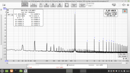
I took all the screenshot's with 1v output / -6dB
But i also attached a shot here, putting out 2.8V @ 1Watt, really nice THD numbers after all!
So i did polute @MagicBus thread here, with this.
So to compensate a bit for this i just wanna tell that i'am waiting for my own designed 😵 LT3045 and LT3094 TO220 (LM7809 / LM7909) pcb's.
I have the chip's on hand now, so looking forward to see if i can make them work as expected, and replace the LM's on Magic's board.
Jesper.


The result is kind of much better now.
If i move the trafo away from the chassis, the 250, 350, 450Hz etc... dissapears.
So i turned it 180C, and moved it as long as possible away from the output terminals.
(I forgot to take a screenshot when trafo was moved aeay from chassis)
I took all the screenshot's with 1v output / -6dB
But i also attached a shot here, putting out 2.8V @ 1Watt, really nice THD numbers after all!
So i did polute @MagicBus thread here, with this.
So to compensate a bit for this i just wanna tell that i'am waiting for my own designed 😵 LT3045 and LT3094 TO220 (LM7809 / LM7909) pcb's.
I have the chip's on hand now, so looking forward to see if i can make them work as expected, and replace the LM's on Magic's board.
Jesper.
Attachments

Yes i use the CT to also connect to chassis. I moved it to a new point, away from "signal gnd".Jesper, your clone amp appears to use the same screw terminal for both the transformer secondary CT and the link to chassis ground - is that correct? Does the signal input ground itself at the input socket, or via the pcb to that power supply screw terminal ? The speaker outputs appear to be connected to ground through the pcb somehow. Is there a link to that pcb to show its trace outline?
If i disconnect this wire, the 50Hz increase some 10-15dB.
Unfortunately i don't have any pcb outline drawing.
Jesper.
Much better now! And no, not polluting at all. It is a practical application of the project, a test under real conditions. Having access to measuring gear -now possible for low budget DIYers- makes troubleshooting much easier, let alone remote support. 😉 So, for more info on how the transformer was the obvious culprit you can read here : https://sound-au.com/articles/intermodulation2.htm BTW the balanced input has low enough IMD to ensure a clear view of the DUT output.
Waiting for the regs upgrade!
Waiting for the regs upgrade!
Attachments
Hello here... and happy long weekend for them who use this 😎
My measurement's are taken with following specs. :
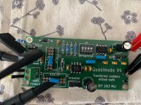
And yes, i looked at "other" design's, using my good eye's and copyeid much of what i found regarding layout etc... - But i won't be selling or something, just for my own use.
The LT3045/LT3094 board's was tested with my scope and a DMM, regulation was good, and no noticable noise. (I did not intensively test them)
In situ i also measured the -9vdc & +9vdc to be sure it did not change during use, which they didn't, soo seems to be working as expected.

And installed inside the Behringer.

As i see it looking at the loopback's, there is absolutely no need bothering using better regulator's than the "stock" LM7809, LM7909 ones.
I belive thoose topnotch opamp's have such good PSSR and stuff that they don't really care 🙂
Well, the one's i made, they will stay in, but as i said, don't bother.
When i have setup the equipmen't today, i ran some test with @YashN mod too.
It's been some time since i last used this mod (my Right input), and the result's are excellent.
Comparing it all is told by the text giving the attached picture's here also.
I'am so glad i build this handy tool, allready used to optimise my labamp. and stuff.
Really a nice piece of equipment, very good to have on hand when doing stuff and building amp's. like i do 🙂
Jesper.
My measurement's are taken with following specs. :
- Victor's at ~1.0 ---> 1.2v 1KHz sine
- Victors PSU is normal regulated linear psu
- Behringer is powered directly from PC usb port
- CloneAmp for comparing YashN's mod to the Balanced input is at input 0.625v (i don't bother to make voltage dividers today)
- I prefer using my Behringer around -6dB as i see best numbers there all-around that is
- Today all measurement's was with my PC (Laptop) psu plugged into the main's (Normally it doesen't do much difference)
And yes, i looked at "other" design's, using my good eye's and copyeid much of what i found regarding layout etc... - But i won't be selling or something, just for my own use.
The LT3045/LT3094 board's was tested with my scope and a DMM, regulation was good, and no noticable noise. (I did not intensively test them)
In situ i also measured the -9vdc & +9vdc to be sure it did not change during use, which they didn't, soo seems to be working as expected.
And installed inside the Behringer.
As i see it looking at the loopback's, there is absolutely no need bothering using better regulator's than the "stock" LM7809, LM7909 ones.
I belive thoose topnotch opamp's have such good PSSR and stuff that they don't really care 🙂
Well, the one's i made, they will stay in, but as i said, don't bother.
When i have setup the equipmen't today, i ran some test with @YashN mod too.
It's been some time since i last used this mod (my Right input), and the result's are excellent.
Comparing it all is told by the text giving the attached picture's here also.
I'am so glad i build this handy tool, allready used to optimise my labamp. and stuff.
Really a nice piece of equipment, very good to have on hand when doing stuff and building amp's. like i do 🙂
Jesper.
Attachments
My measurement's are taken with following specs. :
- Victors PSU is normal regulated linear psu
- Behringer is powered directly from PC usb port
- Today all measurement's was with my PC (Laptop) psu plugged into the main's (Normally it doesen't do much difference)
OK, very cool (cloneAmp for that comparison of Single-Ended vs Balanced measurements is very nice too!). Missing: is the AC mains for the laptop on the same distribution as the Regulated Linear PSU for Victor's Osc?
And yes, i looked at "other" design's, using my good eye's and copyeid much of what i found regarding layout etc... - But i won't be selling or something, just for my own use.
The LT3045/LT3094 board's was tested with my scope and a DMM, regulation was good, and no noticable noise. (I did not intensively test them)
As i see it looking at the loopback's, there is absolutely no need bothering using better regulator's than the "stock" LM7809, LM7909 ones.
I belive thoose topnotch opamp's have such good PSSR and stuff that they don't really care 🙂
Good point about the op amps' specs.
For the Regulators themselves, at that level of performance of the LT3045s, it is absolutely crucial to make excellent PCB layouts. Anything other than that, including all other layouts you see on PCBs here and there (eBay, etc...) will drastically reduce measured performance compared to the datasheet specs.
Oh thanks for testing that. Surprisingly good for single-ended when measuring the clone amp.When i have setup the equipmen't today, i ran some test with @YashN mod too.
It's been some time since i last used this mod (my Right input), and the result's are excellent.
Awesome work, Jesper. Enjoy!I'am so glad i build this handy tool, allready used to optimise my labamp. and stuff.
Really a nice piece of equipment, very good to have on hand when doing stuff and building amp's. like i do 🙂
Hi...
@YashN i was waiting for your'e reply 🙂
I use the same "Line", "Fase" in my Lab. We have 3xLine (R,S,T & L1, L2, L3) + N and PE (Gnd) which gives us when transformers here in DK are in "Star" connection : 3x400vac (50Hz) and 3x230vac (50Hz). The PSU to the Victor's are on the same Line within 1meter of my PC.
- The result's are allmost 100% identical between your's mod and my Magically @MagicBus board on my CloneAmp.
One of the day's i will try it with a voltage divider giving my CloneAmp. some more juice to handle, to see if results will be the same as now with ~0.625v
And this is something i really like with my balancedboard, that it can accept many volt's
But a quistion on the wild which i don't know for sure is ? - How much voltage can i feed directly into the balanced board.
@MagicBus did write some time ago, tens of volts, but can i feed it with say 25v maybee 😵... didn't try, and will not before i know!
Thank's for the reply.
Jesper.
@YashN i was waiting for your'e reply 🙂
I use the same "Line", "Fase" in my Lab. We have 3xLine (R,S,T & L1, L2, L3) + N and PE (Gnd) which gives us when transformers here in DK are in "Star" connection : 3x400vac (50Hz) and 3x230vac (50Hz). The PSU to the Victor's are on the same Line within 1meter of my PC.
This is something i like; because it just verify my theory that when we use equipment below the THD "floor" of the measured DUT, we should get the same result.Oh thanks for testing that. Surprisingly good for single-ended when measuring the clone amp.
- The result's are allmost 100% identical between your's mod and my Magically @MagicBus board on my CloneAmp.
One of the day's i will try it with a voltage divider giving my CloneAmp. some more juice to handle, to see if results will be the same as now with ~0.625v
And this is something i really like with my balancedboard, that it can accept many volt's
But a quistion on the wild which i don't know for sure is ? - How much voltage can i feed directly into the balanced board.
@MagicBus did write some time ago, tens of volts, but can i feed it with say 25v maybee 😵... didn't try, and will not before i know!
Thank's for the reply.
Jesper.
DC limit is your input capacitors specs. AC -with attenuator full open- is limited by the clamping diodes. BAV199 are supposed to withstand 100V but there is no reason to try that... Always use the attenuator to keep it bellow 0dB digital clipping. You can scale down a lot of input signal this way.
OK.Hi...
@YashN i was waiting for your'e reply 🙂
I use the same "Line", "Fase" in my Lab. We have 3xLine (R,S,T & L1, L2, L3) + N and PE (Gnd) which gives us when transformers here in DK are in "Star" connection : 3x400vac (50Hz) and 3x230vac (50Hz). The PSU to the Victor's are on the same Line within 1meter of my PC.
This is something i like; because it just verify my theory that when we use equipment below the THD "floor" of the measured DUT, we should get the same result.
Yes, that's a great observation.
Hello here...
@YashN
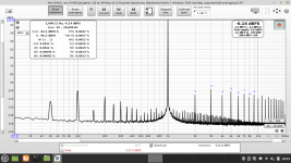
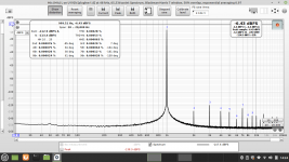
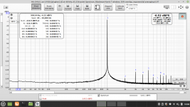
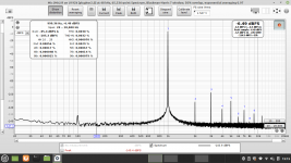
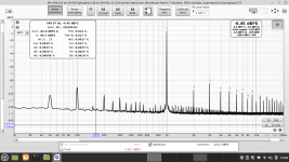
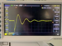
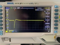
In meantime i had my Quasimodo jig ready and having it working i tested the CT transformer in my famous 🙂 CloneAmp.
Eventhrough i hoped that it would cure more of the 100Hz spikes, it certanly does a really good job, stopping the ringing in the transformer.
I did a FFT before i installed the snubber's, and a new FFT after, within 90min (Sunday morning), so the comparing should be verified as good i think.
Pictures speak for themself.
Rgds; Jesper.
@YashN
I know, i know.. but i think i did an okay layout, looking at the datasheet, also picking the "correct" component's... Well i can't do better, and those little LT's are the limit for soldering i have. - Guess i will never find out 😵For the Regulators themselves, at that level of performance of the LT3045s, it is absolutely crucial to make excellent PCB layouts. Anything other than that, including all other layouts you see on PCBs here and there (eBay, etc...) will drastically reduce measured performance compared to the datasheet specs.
In meantime i had my Quasimodo jig ready and having it working i tested the CT transformer in my famous 🙂 CloneAmp.
Eventhrough i hoped that it would cure more of the 100Hz spikes, it certanly does a really good job, stopping the ringing in the transformer.
I did a FFT before i installed the snubber's, and a new FFT after, within 90min (Sunday morning), so the comparing should be verified as good i think.
Pictures speak for themself.
Rgds; Jesper.
Attachments


It would be interesting to measure the PSSR and other characteristics and compare to the manufacturer's datasheet specs 😉i think i did an okay layout, looking at the datasheet, also picking the "correct" component's... Well i can't do better, and those little LT's are the limit for soldering i have. - Guess i will never find out 😵
Are you able to make another measurement of when the snubber is disconnected again - making sure that no leads are moved, or any other changes made than just breaking the connection at the snubber parts?
It just seems unreal to me that your harmonic levels would change by that level.
It just seems unreal to me that your harmonic levels would change by that level.
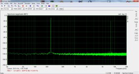
Testing a pure Digital Signal generation and analysis chain, much like what we're doing in the analogue world, except this is all my code running on my laptop:
Checking out harmonics introduced by a low complexity Digital Distortion:

In Green: original Sine input signal. In Blue, Harmonic Response after distortion.
From there, I can tweak the Distortion methods to my liking, listen to them and also visualise what they do in terms of wave shape and harmonics introduced.
A step towards more Virtual Analogue work.
Checking out harmonics introduced by a low complexity Digital Distortion:
In Green: original Sine input signal. In Blue, Harmonic Response after distortion.
From there, I can tweak the Distortion methods to my liking, listen to them and also visualise what they do in terms of wave shape and harmonics introduced.
A step towards more Virtual Analogue work.
I will have this in mind, when i do the next snubber experiement on another amp. or like.Are you able to make another measurement of when the snubber is disconnected again - making sure that no leads are moved, or any other changes made than just breaking the connection at the snubber parts?
It just seems unreal to me that your harmonic levels would change by that level.
But i was very carefull, not making other changes than soldering the capacitor's and resistors on the sec. wires on the transformer.
But your'e right, a bit of wire moving or like could make a difference.
Well, the noisespikes below -110dB are reduced a lot, not that it could be heard, but still the improvement are great.
When i do the snubbering on my next piece of equipment, it would be interesting to see if numbers are getting that much better ?
Looking forward to see that.
Jesper.
Jesper, helloIf i move the trafo away from the chassis, the 250, 350, 450Hz etc... dissapears.
So i turned it 180C, and moved it as long as possible away from the output terminals.
I wrapped self adhesive thin copper tape around a 300VA toroid in an old diy amp hoping to form a Gauss band shield. It improved SNR by 10dB. A very cramped amp due to shoebox size chassis. The 90s made so so quality toroid was interfering a lot. So keep this technique in mind as well.
Attachments
Can you elaborate on the 10dB SNR improvement related to toroid screening? Was that related to specific frequencies?
- Home
- Design & Build
- Equipment & Tools
- Behringer UMC 202HD for measurements